
Define the sensor relationship before choosing datums
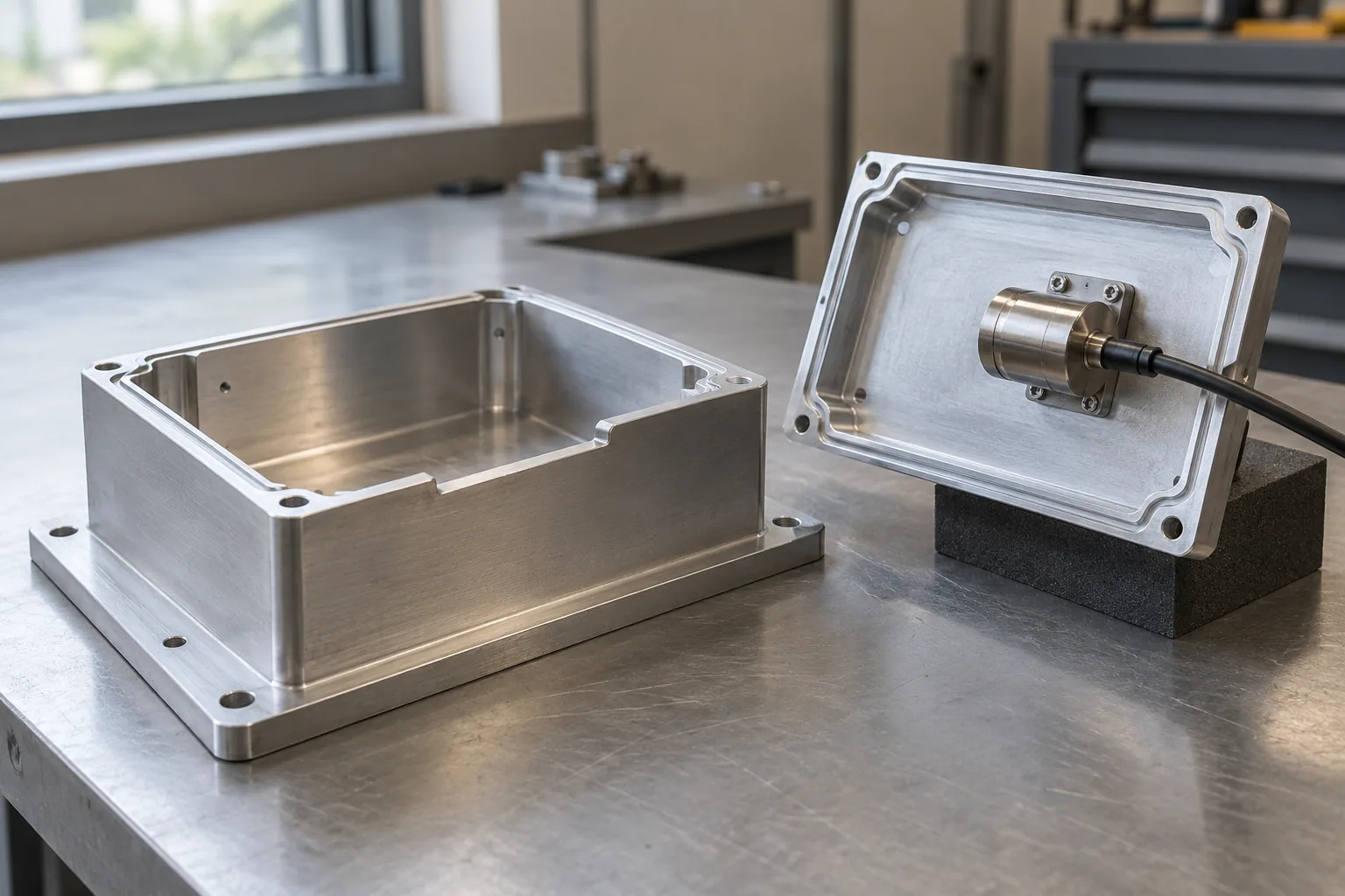
Consider a hypothetical machined housing with a cover carrying an internal sensor. The housing attaches to an external mounting interface, while the cover places the sensor inside the cavity. If the cover shifts or tilts, the sensor may miss its intended position relative to that external interface even when each part satisfies its own drawing.
Functional requirement: the sensor's active location and orientation must remain within the application's permitted alignment envelope relative to the external mount after assembly. The envelope means the allowed movement and tilt, not an assumed tolerance value. Define which directions matter and what an out-of-position sensor would do in the actual application; this hypothetical example establishes neither a sensor specification nor an observed failure.
A datum is an ideal reference established from selected physical features for describing and checking geometry. Begin with the mounting relationship the product must maintain, then ask which housing and cover surfaces actually carry that relationship. An easily accessible machining face can be convenient without representing the installed position.
Ask the application owner to identify the alignment limit, the installed mounting condition and the state in which acceptance is assessed. If those answers change under operating conditions, include that change in the requirement before assigning drawing controls.
Trace the locating contacts through the assembly
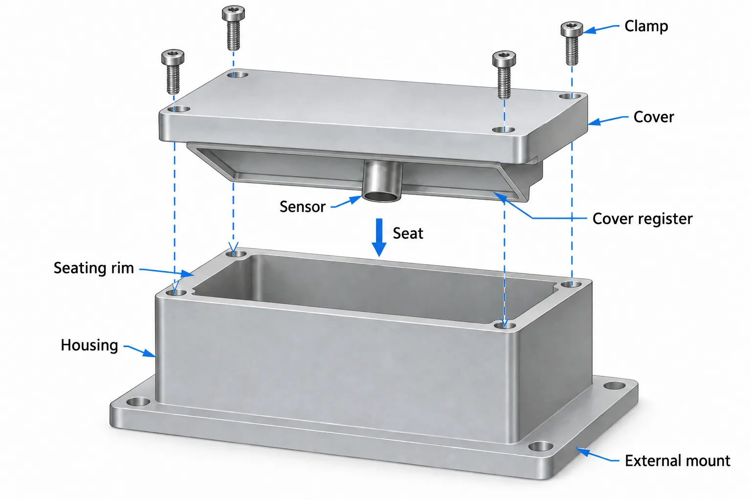
Follow the physical path from the external mount, through the housing, across the cover's locating contacts, and into the sensor attachment. At each transition, ask what stops movement and what could still shift. A seating face can resist tilt when properly contacted; a locating register can restrict sideways movement. Whether that combination suits this housing depends on its geometry and available space.
Fasteners supply clamping force. Clearance around a screw can leave sideways freedom before tightening, so the screw pattern should not be credited with repeatable location merely because it holds the cover down. If a fastener also has a locating role, its fit and contact conditions belong in the alignment model.
The assembly sketch illustrates a proposed cover register and seating rim, with the sensor attached beneath the cover. Its arrows show relationships to review and a seating-before-clamping sequence. It is a conceptual option, not a prescribed datum scheme. Check that the contacts permit full seating without incompatible restraints, and that sensor attachment does not introduce an uncontrolled offset.
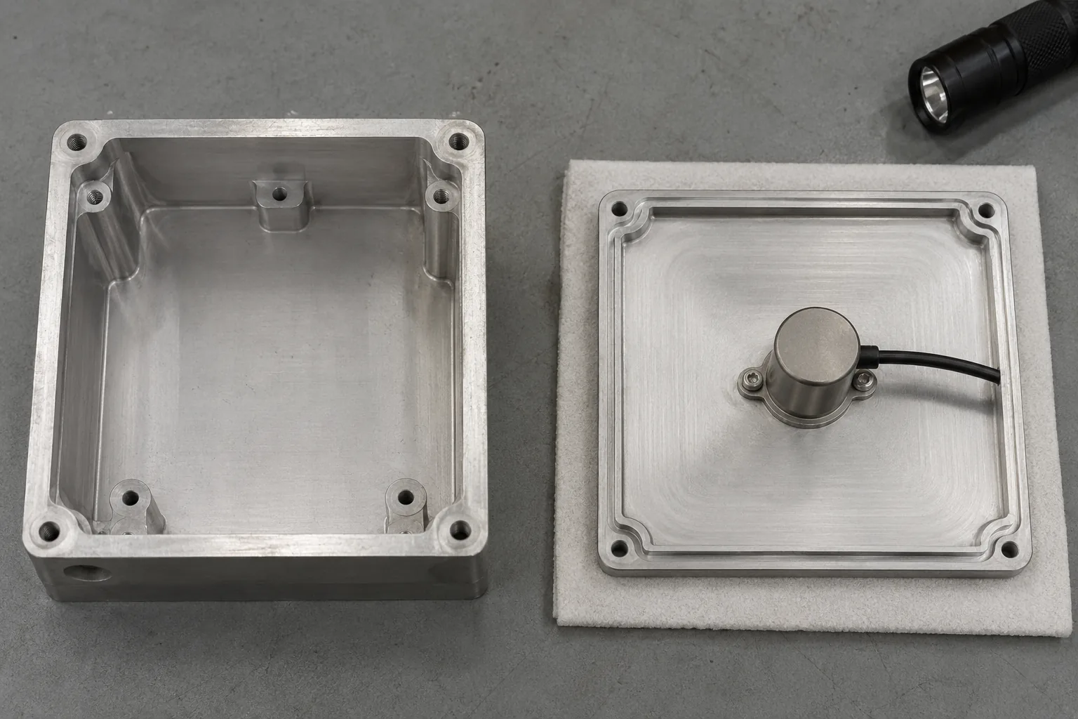
For a physical review, observe which surfaces touch before clamping and whether the cover can rock or slide while seated. Then compare the drawing references and inspection setup with those contacts. A mismatch warrants revising the reference strategy; stable contacts with a displaced sensor point toward other contributors instead.
Build the chain and allocate the useful variation budget
The conceptual chain combines the housing locator's relationship to the external mount, movement permitted at the cover register, the cover's relationship to the sensor attachment, and the sensor's active location within that attachment. Tilting at a seating face also matters when it moves the sensing location away from its target. Follow each relevant direction separately before combining position and orientation effects.
Read the chain in a chosen alignment direction, starting at the external mounting reference. A housing locator displaced relative to that reference carries the cover with it; clearance at the cover fit lets the cover move again; the sensor attachment then determines where the sensing location sits within the cover. A signed path means tracking whether each movement pushes that location toward the same side or the opposite side of the target. Opposing movements may cancel in a particular assembly, but that cancellation is not a reliable basis for interchangeable parts. Assign the available alignment margin to the relationships that actually move the sensing location, including angular effects where they matter.
If sideways freedom at the housing-to-cover fit is the main contributor, control that mating relationship or revise the locator to constrain the relevant movement. If uneven contact allows the cover to tilt, first establish dependable seating; specifying smaller dimensional variation elsewhere will not cure rocking. When the sensor attachment contributes most of the displacement, focus controls on its position relative to the cover's locating contacts instead of demanding precision from unrelated housing features. The drawing and inspection method should therefore connect the external mount to the housing locator, characterize the cover's permitted movement and seating, and relate the attachment to the cover references. Ask the supplier for capability evidence before committing to tighter fits or more demanding geometric controls. If the resulting fixed chain remains impractical, consider deliberate sensor setting only where access, functional checking and retention support it; confirm the chosen approach in assembled conditions.
No numerical allocation follows from this scenario. Complete geometry, material, part scale, operating environment, fastening sequence, process, quantity and measurement method are needed to set limits. Exclude a feature only with a reason tied to the selected relationship; apparent distance from the sensor is not proof that its effect is negligible.
Choose between interchangeable location and deliberate adjustment
Prefer repeatable locating interfaces when replacement covers must fit without individual alignment work and the geometry can be manufactured and inspected practically. This shifts effort toward controlling the contact features and their relationships. A register that consumes unavailable packaging space or cannot be reached by the machining process may need a different locating design rather than a tighter requirement.
Adjustment can be appropriate when the assembly permits accessible setting, a reliable functional check and a way to retain the position through service. It reduces reliance on a wholly fixed dimensional chain, but adds alignment work and verification at assembly. Selective fitting is another deliberate option; it brings part-matching and replacement obligations rather than true interchangeability.
Compare the alternatives against the same sensor use, mounting condition, operating environment and acceptance target. A route that misses the target needs changes to the responsible interface, setting method or control allocation. Once acceptable alignment is demonstrated, compare the complete delivery conditions, including setups, finishing where relevant, inspection, assembly effort and maintenance.
| Decision dimension | Repeatable locating scheme | Deliberate adjustment |
|---|---|---|
| Replacement and assembly | Favor this route when parts must interchange without individual setting; verify across mating combinations. | Use when setting during assembly and subsequent service is acceptable; define how replacement is realigned. |
| Machining and packaging | Review access to the locating surfaces, setup relationships and space consumed by the locator. | Provide reachable adjustment and secure retention; check that the design can move in the required directions. |
| Inspection and acceptance | Relate component measurements to the intended contacts, then verify the assembled sensor relationship. | Check functional position during setting and again after clamping; dimensional records alone do not establish success. |
| Failure response | Identify the dominant contributor before changing its geometry or control. | Determine whether travel, access or retention prevents reliable setting; revise the mechanism or reconsider fixed location. |
Use worst-case and statistical analysis for different questions
Worst-case analysis asks whether the modeled contributors can combine within their permitted bounds to exceed the alignment limit. It is useful when interchangeability must hold across those combinations and distribution evidence is unavailable. For a simple linear relationship, contributions are combined in the unfavorable direction; coupled rotation and contact changes need a model that represents their geometry.
A statistical analysis instead estimates the spread of assembled outcomes under stated production assumptions. It needs evidence about actual variation, centering, dependence between contributors and stability across the intended manufacturing conditions. Contributions created in a shared setup may be correlated, so treating them as independent without investigation can misstate the result.
If a worst-case model fails but a statistical model appears acceptable, identify which assumptions create that difference. Collect representative component and assembly measurements before relying on the estimate. Statistical analysis does not establish that every assembly will pass, and neither method covers an omitted interface or an unmodeled seating change.
ASME Y14.5 provides a framework for stating and interpreting geometric dimensioning and tolerancing, or GD&T. ISO 5459:2024 addresses datums and datum systems within ISO GPS. Use the drawing's governing standard rather than blending conventions; have a qualified reviewer interpret material-condition modifiers and other advanced controls in that specified framework.
Prepare a drawing review that can change the design
Review machining and inspection together. A locator may be reachable for cutting yet awkward to measure after finishing or sensor installation. Ask the supplier how the proposed reference features will be established during setup and verification, and whether those conditions represent the intended assembly contacts. No particular tolerance is established as achievable until that review is complete.
For a quotation or prototype review, share the project inputs below with the designer and machining supplier. Use their responses to agree on a locating concept, contributor controls and an acceptance method before releasing drawings.
- Complete mating drawings and assembly geometry, showing how the sensor is attached and replaced.
- The applicable dimensioning standard and qualified interpretation of any advanced control.
- The functional alignment limit and a description of the consequence of exceeding it.
- The selected contact features, their locating roles and freedom remaining before fastening.
- The fastening sequence and a way to check seating and movement caused by clamping.
- Material, part scale, operating conditions and any effects that could shift the sensing location.
- The proposed measurement method, access and fixture references for parts and the finished assembly.
- Intended quantity, manufacturing route, relevant capability evidence and service expectations.
Frequently asked questions
Can a supplier's fixture define the housing's functional datums?
A manufacturing fixture can help establish the specified references, but convenience alone does not make its contacts functional. Ask how fixture location is related to the installed mount and how that relationship is checked. If the fixture grips an unrelated surface, assess the transfer error before using its measurements to judge sensor alignment.
Does successful alignment of a prototype justify reducing drawing controls?
A successful prototype shows that its particular parts and assembly method can work together. It does not demonstrate replacement interchangeability or the range of intended production conditions. Examine whether hand setting or part matching contributed to the result, then obtain evidence for the proposed broader assembly route before relaxing controls.
What must be revalidated when a locating interface changes after supplier review?
A locator revision can invalidate evidence gathered for the previous geometry. Trace which housing and cover callouts depend on the changed contact, and align the mating drawings so they describe the same revised relationship. Ask whether the supplier's earlier setup and measurement evidence still applies; obtain new evidence where the contact or manufacturing approach has changed. Recheck sensor alignment using the intended seating and fastening sequence, including replacement-cover compatibility if interchangeability is required. Proceed toward release only when the revised documents, capability evidence and assembly check agree; unresolved differences require another design decision.