
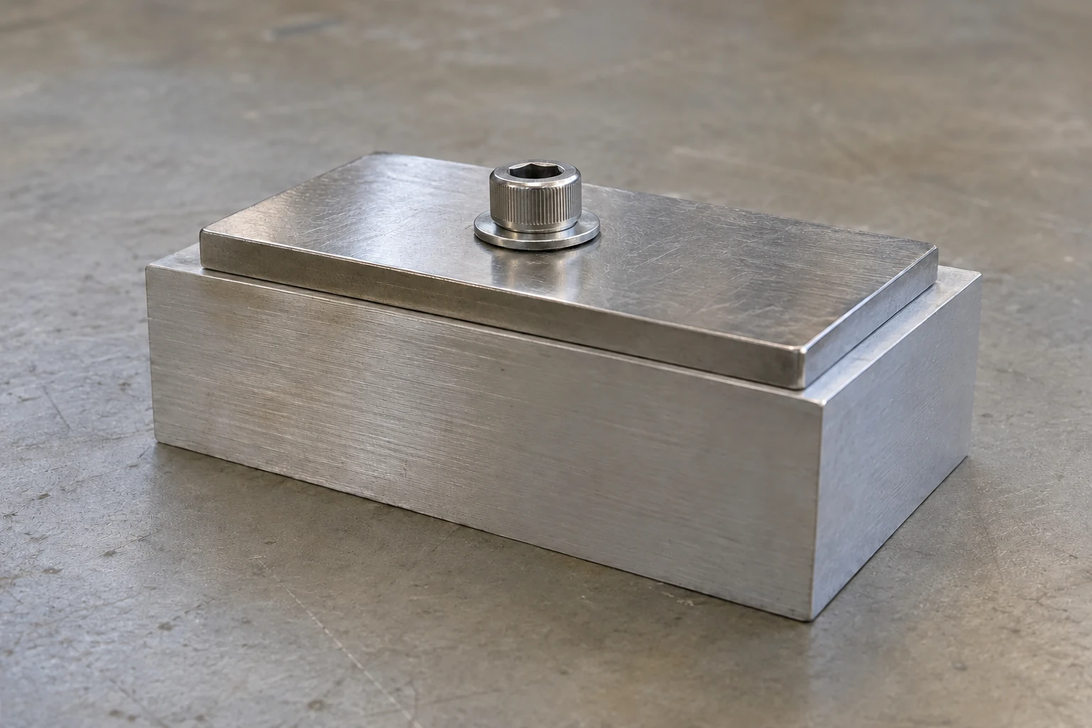
The depths that must be distinguished
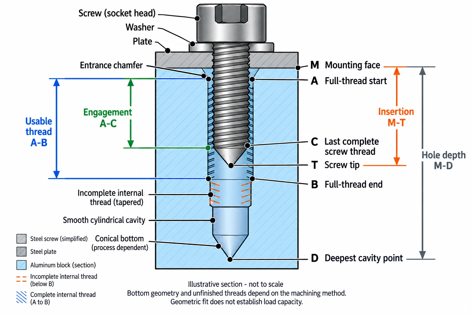
A blind threaded hole stops within the block. Its drilled depth describes the cavity, while its usable thread depth describes the fully formed internal threads available to mate with the screw. Engagement is the overlap between those internal threads and the screw's complete external threads after assembly. These lengths answer different questions.
Start the section view at the block's mounting face. Identify the entrance chamfer, where the full internal thread begins, where it ends, and the geometry beneath it. The chamfer eases entry but removes part of the potential engagement. An incomplete thread near the bottom is a transition, not an extension of the usable region.
State whether hole depth ends at the full-diameter cavity or at the deepest point. A drill-point cone, when present, provides less room for a screw tip than its deepest point suggests. The bottom shape and unfinished-thread region depend on the chosen machining method. Show them as conditional geometry in an illustrative section, then replace them with the supplier's confirmed arrangement for the production drawing.
Check the installed screw envelope
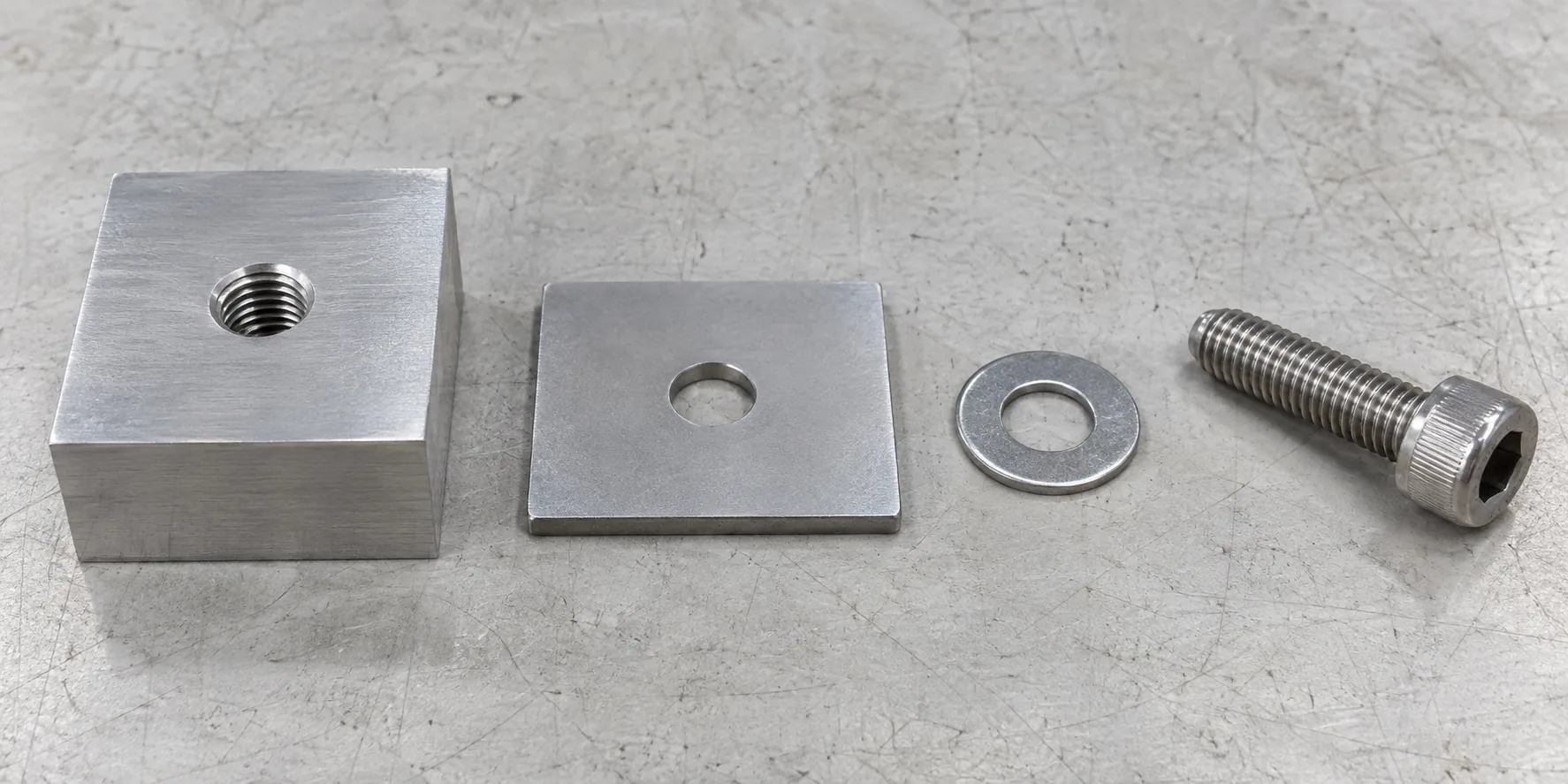
For a hypothetical mounting joint, the screw head bears on a washer above a clearance hole in the plate. Its threaded end enters the aluminum block. The plate and washer establish how much screw length remains below the mounting face. A recessed seat or a different head changes that reference, so use the selected fastener's actual length convention.
At nominal conditions, locate the screw end and the overlapping complete threads. Then examine the allowed variations. A longer screw combined with a thinner clamped stack tends to project farther into the block. A shorter screw with a thicker stack tends to reduce engagement. Account for the screw's incomplete tip threads and any unthreaded shank; insertion length alone can overstate the mating thread length.
Compare the maximum screw envelope with every possible obstruction, including the bottom transition and remaining cavity. Separately compare the minimum complete-thread overlap with the required engagement. The drawing must satisfy both checks. If the end reaches an obstruction before the head seats, tightening resistance can rise while the plate remains inadequately clamped.
Use the actual tolerances in the assembly model rather than an invented example dimension. Check the nominal configuration for intended fit and the limiting configurations for clearance and engagement. Include washer thickness, seating details and any change in stack thickness during installation where applicable.
Communicate a hole the supplier can manufacture and inspect
For a non-dimensional section-view example, use these callouts: 'M - Mounting face (depth datum)'; 'A - Full-thread start'; 'B - Full-thread end'; 'C - Last complete screw thread'; 'T - Screw tip'; and 'D - Deepest cavity point'. Label A-B 'Usable thread', A-C 'Engagement', M-T 'Insertion', and M-D 'Hole depth'. In this illustrated assembly, the screw's complete threads begin above A, so A-C is the mating interval; if an unthreaded shank extends below A, the overlap starts farther into the block. Require the shortest permitted overlap to meet the project's calculated engagement requirement. For the deepest installed screw position, check M-T against the accessible cavity envelope, including unfinished threads and bottom shape, rather than treating M-D as unobstructed cylindrical space. The example chooses the deepest cavity point as its hole-depth endpoint; it is not a dimensioned production specification. Have the supplier confirm the entrance, full-thread limits and bottom arrangement for its process, and assess load capacity separately.
Protolabs describes an internal-threading service using a single-lip tool rather than a traditional tap. Its published standard-hole guidance also notes that surrounding features, lead-in treatments and fixturing can reduce thread-depth capability. Those are bounded service examples: ask your selected supplier how its proposed method reaches the required region.
For cutting taps, chip evacuation and the tool's lead must be considered along with the pilot hole. Sandvik Coromant's tooling discussion identifies chip-control problems and contact with the hole bottom as issues in blind-hole tapping. Thread milling or another selected approach has its own reach and access constraints. A bottoming tap does not eliminate all clearance requirements.
Before quotation, resolve the following items together. A change in tooling may alter the unfinished region or inspection access without changing the joint's functional requirement.
- Thread identity: specify designation, pitch and class consistently on the drawing and model.
- Usable region: identify its start and end from a named surface, excluding entrance and bottom transitions.
- Assembly definition: provide the screw specification, length convention, plate stack, washer and seating details.
- Hole limit: define the depth endpoint and material that must remain below and beside the feature.
- Process feasibility: ask about approach direction, tool reach, pilot geometry and chip handling for the proposed method.
- Acceptance evidence: agree how complete threads, available clearance, cleanliness and assembly seating will be checked.
Choose a correction that preserves engagement and material
If the current screw projects too far but has spare usable overlap, a shorter available screw is a practical first option. It reduces the bottoming risk without removing more block material. Recheck the thick-stack condition before selecting it. If that leaves too little engagement, the joint geometry needs another route.
Deeper machining can preserve screw availability when there is enough material beneath the hole and the supplier can produce the required thread. It also moves the cavity closer to the opposite face or adjacent features. Where the wall is already constrained, revising the stack or local block geometry is preferable to extending depth without a material review.
Compare feasible routes for the same attachment function and load requirements. Retain only those that satisfy the engagement, clearance and wall constraints. Then compare screw availability and the complete delivery effort, including tooling, inspection and assembly handling. A less demanding depth may simplify production, but it does not establish a price or lead-time saving.
| Review finding | Route to evaluate | What could rule it out |
|---|---|---|
| Screw-end interference with adequate engagement reserve | Select a shorter screw and repeat the limiting-stack checks | The available length loses required complete-thread overlap. |
| Required overlap needs the present screw projection | Extend compatible hole and thread geometry | Insufficient bottom material, adjacent features or tool access. |
| Neither screw shortening nor extra depth satisfies the joint | Revise the plate stack or mounting-block geometry | Functional interfaces or the strength review reject the change. |
Verify seating, acceptance and joint strength separately
During prototype assembly, use the intended screw and stack with a clean hole. Observe whether the plate seats as expected and whether tightening resistance develops before seating. Unexpected resistance warrants inspection for an interfering screw end, chips, damaged threads or an incompatible fastener; that observation alone does not identify the cause.
Reconcile the machined part with the section drawing and the supplier's agreed inspection method. A thread gauge establishes only the characteristics it is intended to check; its reach and reading need not establish all usable depth or screw-end clearance. Use complementary depth evidence and an assembly check where those properties govern acceptance.
Geometric fit does not demonstrate fastening performance. A joint-strength review also needs the aluminum material and condition, fastener properties, service loading, installation torque and relevant operating conditions. More engagement does not increase capacity proportionally in every joint, and a diameter-based rule cannot cover every material and load case. If the required capacity is unverified, retain that boundary while assessing the fit.
Prepare the section drawing, assembly model, fastener information, stack tolerances, remaining-wall constraints and any prototype seating observations for a combined supplier review. Add the service-load and installation inputs for the strength assessment. These records allow the team to choose a screw and manufacturable hole together, or identify the geometry that must change before production.
Frequently asked questions
Why can a prototype assemble normally while a later build bottoms out?
An initial sample may not represent the longest screw, thinnest stack or shallowest permitted cavity. A later combination can consume the clearance that existed in the sample. Recreate the permitted dimensional extremes rather than using a successful assembly as proof for the entire tolerance range.
Can adding a washer solve bottoming?
A washer can reduce screw projection by increasing the clamped stack, but it also reduces thread engagement and may change seating or the required fastener length. Treat it as an assembly change with its own tolerances and suitability review, rather than an automatic repair.
What evidence distinguishes bottoming from damaged threads?
Compare the location of the resistance with the screw's calculated installed position, inspect the hole and fastener, and look for corresponding contact marks or debris. Thread damage can cause resistance before the screw reaches its intended seat. Keep the cause open until the geometric and physical evidence agree.
Should the drawing mandate tapping?
Specify a process when it is functionally necessary or required by the agreed acceptance method. Otherwise communicate the needed thread geometry and let the supplier propose a compatible approach. Evaluate the proposal against access, bottom clearance and inspection needs before accepting a process substitution.