
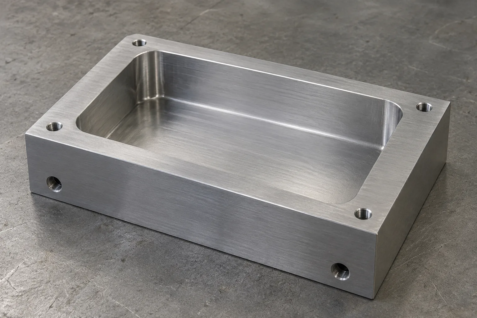
Start with the mating component, not a radius rule
The useful corner change is the one that leaves the fixture doing its intended job. For a recessed component seat, establish where the mating part rests, what stops its movement, and which surrounding regions simply provide clearance. These roles can coexist in the same pocket, but they need different design protection.
Consider a hypothetical CAD review of an aluminum base with a deep seat. Assume the floor supports the mating component and selected straight wall regions locate it, while the corners have no intended contact. A larger radius may be acceptable if the component still enters and seats fully. Local relief may suit a projecting mating corner where rounding the whole transition would remove required clearance. These are design assumptions to test, not observations from a delivered fixture.
Overlay the mating envelope in its assembled position and examine the insertion path as well as the seated condition. Mark the actual contact faces and permitted change zones. If the drawing follows the mating outline closely, investigate whether that outline expresses a necessary constraint or merely inherited geometry; either explanation is possible.
Why depth makes a small corner more demanding
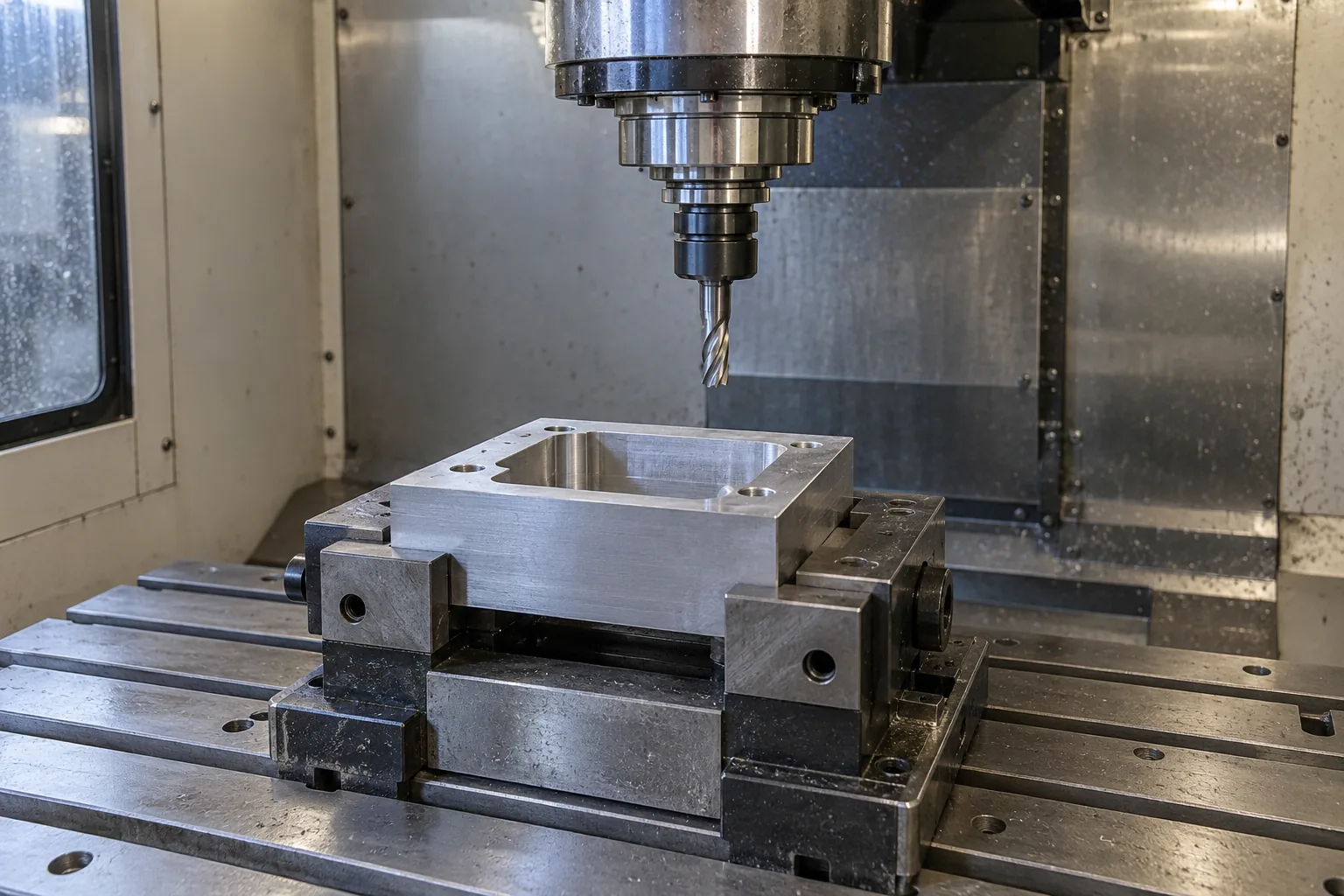
In deep-pocket CNC machining, a tight internal corner can limit the cutter diameter that will fit its final contour. Reaching the bottom of a deep seat may then require more tool length beyond the holder. That exposed length, called overhang, lets the cutter bend more readily under cutting load. Vibration or tool deflection can make wall finishing harder, depending on the cutting conditions and the rigidity of the setup.
The pocket opening also has to clear the holder and the noncutting part of the tool. A cutter may have the right nominal diameter yet lack suitable cutting length or assembly clearance. A narrow entrance can prevent a larger tool from reaching a roomier region below. Depth, opening, and corner contour therefore belong in the same access review.
Ask the supplier to check the proposed cutter, holder, approach path, and clamped workpiece together. Include access for chip removal and finishing at the floor-to-wall transition. If increasing the radius permits a more rigid assembly but the holder still cannot enter, the redesign has not solved the controlling restriction. There is no universal depth-to-diameter capability limit for every machine and setup.
Choose the corner alternative by function
Enlarging a continuous internal radius leaves more material across the corner transition. That can open up cutter options, but it can also intrude into the space required by a relatively square mating corner. Local relief instead removes material in an approved corner zone so the mating outline can clear while adjacent straight locating faces remain.
Choose between these alternatives by the contact pattern and available clearance, then assess their machining consequences. Relief near a loaded wall or support land can reduce useful material; its shape may also affect cleaning or tool access. The designer must approve those effects. Ordinary end milling leaves a curved internal corner, so a mathematically sharp corner is not a realistic promise for that operation.
| Design option | Condition that favors it | Functional risk to examine | Supplier question |
|---|---|---|---|
| Retain the specified corner | The surrounding contour is essential to fit or positioning, with no approved change zone. | A machining-driven revision would alter the intended contact or assembly envelope. | Can the unchanged requirement be reached, finished, and inspected with the proposed equipment? |
| Increase the continuous radius | The mating part has room around the transition and useful wall contact remains. | The larger arc may obstruct insertion or shorten a locating face. | Does the revised contour allow a more stable tool assembly without introducing another access restriction? |
| Add localized corner relief | Interference is concentrated near a mating corner, while adjacent wall regions need protection. | The cutout may weaken a nearby feature, collect debris, or extend outside the permitted zone. | Can the relief be produced and deburred while preserving the specified supporting geometry? |
Keep workholding, finishing, and inspection in the decision
Holding the base securely during machining is a separate problem from locating the component in use. Pocket changes can leave thinner walls or reduce material available for clamping. Review the cutting setup against the external datums, clamp locations, and wall and floor requirements; an easier corner toolpath can still demand careful support elsewhere.
Critical faces may need finishing passes whose tool access differs from rough material removal. A relief can add an edge that needs deburring, while a larger radius can change how a finished wall is approached. Discuss the required surface finish and treatment along with the alloy and stock condition, rather than assuming all aluminum bases behave alike.
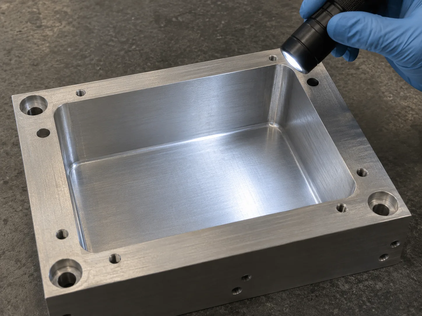
Inspection needs its own physical access. A virtual cutter path through CAD does not establish that a probe, gauge, or other agreed method can reach the acceptance feature and reference its datum. Ask how the locating faces and seat will be evaluated after finishing. If the intended method cannot reach them, resolve the measurement approach or the permitted geometry before accepting the variant.
Compare quotations on equivalent fixture requirements
For a low-volume base, stock preparation, programming, setups, tooling, and inspection can matter alongside cutting time. Longer reach may require a cautious machining strategy or additional finishing work. Conversely, an alternative contour that fits existing equipment may simplify the route without removing every costly operation.
Request separate offers for the retained drawing and each approved variant using the same mating purpose, service loads, environment, and acceptance targets. Keep material, finish, quantity, and delivery objectives aligned. Ask the supplier to identify the operations changed by the redesign, including tools, workholding, edge finishing, and verification, rather than inferring savings from the model alone.
If a variant fails the fit or inspection review, adjust the allowed relief or return to the constrained contour. If access remains inadequate, ask for a revised machining route within the same component design before approving it. Once alternatives meet the agreed requirements, compare complete delivery conditions: validation effort, postprocessing, measurement evidence, timing, and any change to cleaning or maintenance in use. A larger radius is not automatically the cheaper accepted part.
Use review evidence to accept, revise, or retain the design
The next decision should follow the restriction actually found. Clear corner space plus a credible improvement in reach favors the larger-radius variant. A local clash beside necessary straight contact favors bounded relief. A loaded region or essential contour that cannot tolerate either change favors retention, even when machining is demanding.
For any accepted candidate, relate the supplier's proposed route back to assembly and acceptance. If a trial is needed, evaluate it under the intended use conditions; convenient bench seating alone does not establish how the fixture performs when loaded. Unexpected contact, inaccessible inspection features, or changed support should reopen the corresponding design choice.
- Trace each support and locating function to its required surface so a negotiable corner is distinguishable from mandatory contact.
- Check the mating shape through insertion and seating, including interference created by added corner material.
- Map the proposed removal against wall thickness and load-bearing regions before authorizing a relief.
- Have the machinist review holder clearance at the deepest required reach with the part clamped as planned.
- Agree on a way to verify the critical geometry from the specified datums after the final surface operation.
- Compare the reviewed alternatives using their complete production and acceptance routes, then record the authorized geometry.
Prepare an RFQ that separates mandatory and negotiable geometry
Send CAD and a controlled drawing together with the mating-part envelope, pocket requirements, locating datums, and permitted relief zones. Include material and stock requirements, critical tolerances, wall and floor requirements, surface finish and treatment, inspection criteria, batch quantity, and the target delivery. Supply controlled variants where changes are allowed; leave essential features clearly identified.
Ask the supplier to explain which access constraint each alternative addresses and what remains difficult. With that review and a functional fit check, you can decide whether to authorize a revised radius, approve local removal, or keep the original contour. Project cost and acceptance remain outcomes of the agreed design and manufacturing assessment, rather than promises attached to a generic corner recommendation.
Frequently asked questions
Can the corner redesign be assessed without the physical mating component?
If controlled CAD or a mating envelope establishes contact and clearance, use that information for a provisional review. If it does not, ask the design owner to identify the intended seating and locating relationships before approving a corner change. Prepare the available mating geometry and mark unresolved interfaces. The supplier can assess machining access while those questions remain open, but that assessment cannot settle assembly suitability.
Does an assembly check with an unfinished sample settle the fit question?
It can reveal obvious interference, but subsequent finishing or surface treatment may affect the accepted mating condition. Evaluate fit at the state specified for delivery and against the drawing's acceptance requirements before using the sample to authorize production.
Does a quoted corner variant count as an approved design?
No. Give each alternative a clear drawing or CAD revision and an approval status, and ask the quotation to identify the version it covers. An unapproved proposal can remain a sourcing option without replacing the released geometry. If the priced and approved versions differ, resolve the mismatch before ordering. This distinction lets you evaluate an offer without treating its price as permission to change fixture function.
What happens if the supplier changes the manufacturing route after design approval?
Compare the proposed change with the assumptions used to accept the variant. Keep the approved geometry, functional review, and supplier feasibility assessment available for that comparison. If different equipment, workholding, or measurement access invalidates an earlier assumption, reopen the affected assessment before proceeding; otherwise, document why the original judgment still applies. An unchanged part drawing alone does not establish that a replacement route remains feasible or preserves the quoted delivery conditions.