
Start with the recessed feature that actually needs the depth
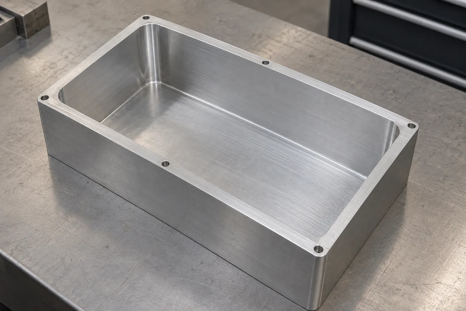
Consider an aluminum or steel enclosure with a component-clearance pocket and a recessed mounting surface. The component may need space below the opening, while only a local seat needs accurate depth and finish. Extending every surrounding surface to that same level can create unnecessary cutting reach.
Separate the space occupied by the component from the surfaces that locate, support, or seal it. If the lower recess serves only clearance, explore a shallower surrounding floor with a local deep region. Keep the original depth wherever reducing it would interfere with the component or its assembly path.
A stepped pocket is useful only when the upper ledge leaves room for the tool to reach the lower feature. Trace the approach from the opening to the deepest cut, including the holder. A ledge that blocks this route can remove the expected machining benefit.
Why reach, corners, and trapped chips change the cut
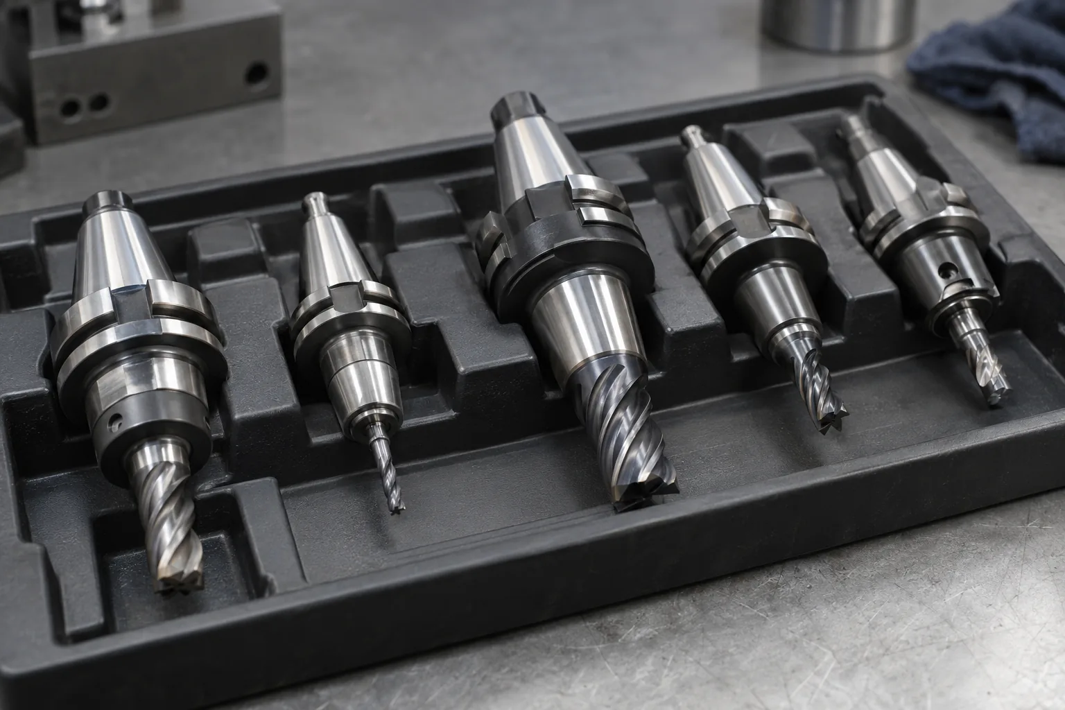
Tool overhang is the unsupported length extending from the holder toward the cutting zone. A deep opening can force that length to increase, especially when the holder cannot enter the cavity. Under a cutting load, a longer or thinner cutter bends more readily. The cutting edge can then move away from its intended path, making wall dimensions and finish less consistent.
Vibration can leave repeating marks on a wall; chips caught in the cavity can be cut again and damage the surface. These are possible mechanisms, not a diagnosis from appearance alone. Ask where the marks occur, whether they change near the bottom, and how they respond to a controlled machining adjustment.
A small internal wall-corner radius limits the diameter of a cutter that can enter it. The supplier may rough the main cavity with a larger tool and use a smaller cutter for the corners, but that smaller tool still needs sufficient reach. Rounded corners therefore influence access as well as the finished outline.
At depth, chips also have farther to travel out of an enclosed space, and coolant delivery can be obstructed. Have the supplier examine the planned entry, cutting engagement, and chip exit route together. Improving stiffness will not solve a chip-removal problem if the cavity still traps the material being removed.
Choose geometry changes by what the enclosure must preserve
Prefer changes inside the existing part when they create a usable tool route without compromising its function. A wider opening may admit a more rigid cutter or holder, while a larger corner radius can reduce reliance on a small finishing tool. Neither change automatically shortens the required reach; inspect the deepest remaining feature.
Opening a side becomes attractive when the surrounding structure can tolerate the opening and the access direction suits the functional surfaces. Splitting the enclosure is a different tradeoff: it can expose otherwise enclosed features, but it introduces joint location, assembly, and sealing questions. Retain a closed, single-piece design when those interfaces would threaten the required function and a reviewed machining route remains practical.
| Design condition | Route to evaluate | Reason and condition that can reverse the choice |
|---|---|---|
| Depth is needed only at a local seat | Stage the floor and retain the local recess | Reduce the region needing long reach; reject the step if it obstructs the cutter or component. |
| The opening is tight but surrounding space is available | Widen the approach | Create room for a larger tool assembly; retain the original boundary if widening harms wall stiffness or packaging. |
| Corner shape has flexibility | Increase internal wall radii | Allow a less slender corner-cutting tool; check mating-part clearance before changing the radius. |
| A side can be opened without losing required function | Provide open access | Make cutting and chip removal more direct; reconsider if the opening removes a sealing land or required support. |
| An enclosed feature is still impractical to reach | Evaluate a split construction | Expose the feature for machining; compare joint tolerances and assembly effort against retaining the single piece. |
Connect the tool route to cost, quality, and delivery
A restricted cavity may need repeated step-down passes, separate roughing and finishing tools, or specialized tooling. Those choices can increase machining time and preparation effort. Geometry that admits a practical cutter can change the strategy, but it does not justify a promised saving without a supplier review.
Apply dimensional and finish requirements to the surfaces that perform a function. A locating wall may need tighter control than a clearance floor. First improve the tool route, then consider whether a nonfunctional requirement can be relaxed; accepting poorer accuracy everywhere can leave the real access problem untouched.
Compare candidate designs for the same use, loading environment, and acceptance criteria. Ask how each route will verify the recessed surfaces, manage any finishing operations, and support repeat orders. For a split design, include joint alignment, assembly, and maintenance rather than comparing machining quotes alone.
If a trial misses wall accuracy or finish, identify whether the limiting feature is reach, corner access, chip removal, or part support before revising the geometry. A localized radius change may address a corner problem; persistent access limitations may instead justify opening or dividing the part. Once the required results are demonstrated, compare the complete delivery scope and tooling availability.
Make the drawing review resolve the difficult features
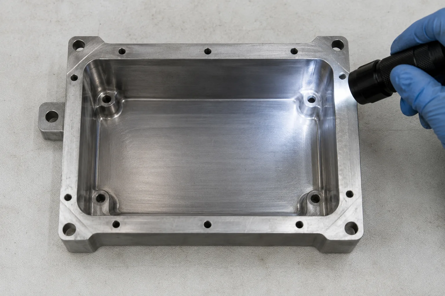
Send a drawing and model that distinguish functional limits from geometry that can change. For deep pocket CNC machining design, nominal depth and width are a starting point, not a complete access assessment. Local constrictions, holder clearance, and the inspection route can govern what is practical.
Ask the supplier to identify the limiting feature and the proposed way to machine and inspect it. If the answer relies on equipment or tooling not yet selected, keep that dependency visible when comparing the design alternatives.
- Mark the deepest functional seat and explain why its position must be retained.
- Show the narrowest opening and any ledges that obstruct entry to lower surfaces.
- Specify internal wall radii and floor transitions so corner access is unambiguous.
- Identify locating, sealing, and clearance surfaces with their respective tolerance and finish needs.
- State the material and relevant condition; obtain a process review for that material rather than assuming aluminum and steel behave alike.
- Provide expected quantity and required delivery timing so tooling preparation can be evaluated.
- Describe allowable access openings, wall changes, and assembly interfaces before requesting redesign advice.
- Agree how recessed dimensions and surfaces will be inspected when direct access is limited.
Prepare the inputs for a focused manufacturability decision
Gather the current model, dimensioned drawing, material specification, component envelope, sealing boundaries, and surfaces that must remain fixed. Add any observations from existing samples, including the location of surface marks or dimensional variation, without assigning an unverified cause.
Use that package to request a focused design-for-manufacture assessment: can the current tool route meet the functional requirements, and which permitted change removes its main limitation? With the reviewed tooling approach and acceptance evidence, you can choose between retaining the cavity, revising its local geometry, opening access, or adding an assembly interface.
Frequently asked questions
Can a successful prototype establish that the pocket is practical for repeat orders?
It shows that the demonstrated setup produced an acceptable sample. Repeatability also depends on tool condition, chip control, and an inspection approach that can detect changes during production. Ask which parts of the prototype method will carry into the quoted supply route.
Does a sharp mating component require sharp corners throughout the cavity?
Not necessarily. A local corner relief may accommodate the component while leaving the main walls suitable for a larger cutter. Review the component's insertion path and any sealing or support surface before adopting that relief.
Will improving the finish specification solve visible vibration marks?
A finish requirement describes the desired result; it does not stabilize the cut. When marks indicate a possible vibration problem, have the supplier examine the tool assembly and engagement before deciding whether a finishing operation is appropriate.
When should electrical discharge machining enter the discussion?
Consider it when an essential enclosed feature remains unsuitable for the reviewed milling approach and the material and feature are compatible with the proposed process. Deep pockets alone do not establish that need. Compare additional process preparation and inspection with permitted geometry changes.