
Define the mounting arrangement and the load that matters
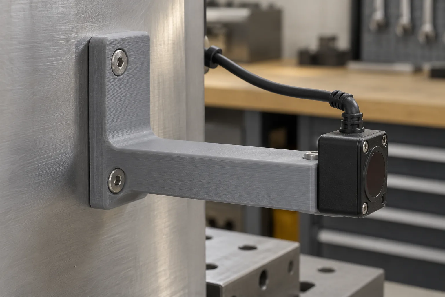
Consider a hypothetical polymer bracket with a vertical mounting leg fixed to a rigid surface and a horizontal arm carrying a sensor near its free end. The sensor applies a downward load. Success means maintaining the sensor's required position while the bracket and its fasteners remain acceptable under the intended service conditions. No load rating or allowable movement is assumed.
The projecting arm acts as a lever: its load creates bending near the junction with the mounting leg. Local tension there can pull on bonds between printed layers, depending on how the bracket was built. A side build is worth evaluating when continuous deposited paths can follow this bent outline; an upright arrangement may place more of that local tension across layer interfaces. The actual toolpath and constraints decide whether this distinction applies.
Draw the load direction on the assembled geometry, then trace how it reaches the mounting surface. Include cable forces or additional service loads if they are present. If those forces change the dominant stress direction, reconsider the initial side-build preference. Mark the surface whose movement affects sensor function, and obtain its acceptance requirement before ranking candidates.
Read directional printed properties as evidence, not a bracket rating
FDM deposits softened polymer along paths and bonds successive layers. The resulting part can respond differently when pulled along deposited material and when pulled across its interfaces. This direction dependence is called anisotropy. It explains why rotating the same bracket can change the relationship between its stressed regions and its printed structure.
Stratasys's PC material data sheet distinguishes printed test orientations and identifies specimen conditions. It describes its typical values as reference and comparison information rather than design specifications or quality-control limits. Use it as an example of how to read directional evidence, without importing its numerical results into this bracket decision.
For the chosen polymer, match the documented grade, machine, specimen orientation, build conditions and conditioning to the proposed process. A mismatch leaves a gap that needs relevant evidence. Bulk polymer properties do not establish printed-component performance, and PC results cannot be transferred to another polymer or machine.
Ask whether the available test measures the behavior that matters here. Tensile data can inform a directional comparison, but the mounted bracket also bends, bears against fasteners and may need to hold position over time. Machine compatibility makes a configuration printable; it does not establish suitability for the sensor's duty.
Compare candidate builds with the same functional requirements
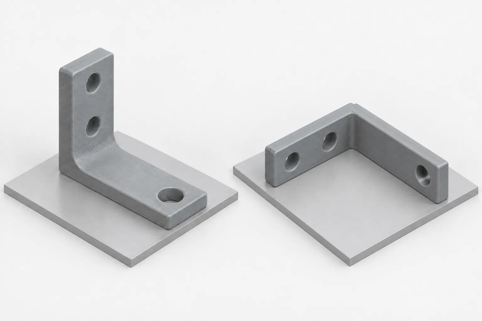
Keep the bracket geometry and intended downward loading unchanged while comparing an upright build, with the arm resting on the build surface and the mounting leg rising from it, against a build resting on a lateral side. The orientation sketches illustrate placement only. They neither show a qualified toolpath nor predict which sample will pass.
Prefer the side candidate when the dominant bending region benefits from paths that continue through the arm-to-leg junction and support removal leaves usable interfaces. Keep the upright candidate in contention when its weaker-direction evidence and component testing satisfy the same duty, especially if it avoids damage or finishing at essential contact surfaces. Missing directional data, another significant load direction or an inaccessible support region can reverse that preference.
| Decision dimension | Side build | Upright build | Evidence that changes the choice |
|---|---|---|---|
| Load path at the bend | Evaluate path continuity along the bracket outline. | Check tension across interfaces at the junction. | Actual deposition paths and matched directional properties. |
| Support contacts | Locate contact regions on the lateral face and holes. | Inspect overhangs and the junction rather than assuming support-free printing. | Sliced support locations and an accessible removal method. |
| Mounting and sensor seating | Assess the faces and openings affected by their rotated position. | Check whether build-surface contact affects arm seating. | Trial assembly, contact condition and required fit. |
| Finishing and inspection | Retain only if cleanup preserves the functional geometry. | Retain only if its accessible surfaces meet acceptance. | Observed support damage, finishing allowance and inspection access. |
| Overall delivery work | Balance mechanical benefit against cleanup and verification effort. | Balance convenient printing against performance evidence still needed. | A comparison covering printing, finishing, testing and recurring inspection. |
Revise geometry when a promising orientation is impractical
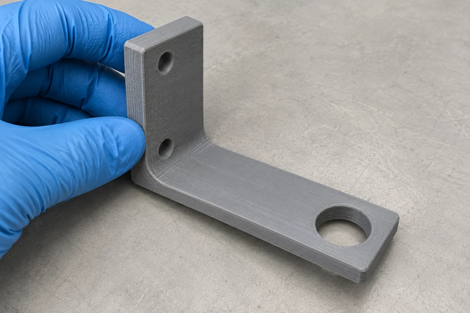
Support removal belongs in the orientation decision because inaccessible material can obstruct a mounting hole or interfere with sensor seating. Scraping a critical contact surface can also change how the assembly sits. Examine the supported regions on a printed trial part and perform a dry assembly before treating a convenient build as a usable bracket.
If the side candidate offers a useful load-path arrangement but leaves a trapped support region, review access openings or the placement of noncritical features. If the bracket moves excessively near its bend, consider changes that redistribute local loading or shorten the unsupported reach, subject to the mounting envelope. These are design options to analyze, not assured remedies.
A rib can alter both the stress distribution and the support plan; additional thickness can change printing and fit. Revisit the affected interfaces and sliced paths after either change. If feasible revisions still leave unacceptable movement, damage or blocked assembly, change the orientation or reconsider the part design rather than relying on higher infill alone.
Validate the printed configuration against its intended service
Test candidate brackets in a fixture that represents the intended mounting surface, fastening arrangement and sensor attachment. Apply the relevant load in the stated direction and observe the sensor location as well as the bracket's bend and attachment points. Use the same acceptance objective for both builds; comparing dissimilar fixtures or finishing states would obscure the orientation effect.
When a sample misses its movement or integrity requirement, distinguish bracket deformation from fixture motion, fastener slip and seating problems before choosing a remedy. A crack near a layer boundary is useful evidence to investigate, but it does not by itself prove that orientation caused the failure. Document where the problem appeared and compare that observation with the load path and printed structure.
A successful short static assessment supports only the conditions actually evaluated. Repeated loading, sustained loading and temperature exposure can introduce different performance demands. Safety-critical service and production consistency require appropriate project-specific qualification rather than extension of a prototype demonstration.
Once candidates meet the relevant requirements, compare the complete delivery conditions: print preparation, support removal, finishing, inspection, qualification work and maintenance needs. Keep printing time and material consumption qualitative until a documented comparison exists. The preferred route is the acceptable configuration with a workable delivery plan, not automatically the shortest print.
Prepare the evidence needed to commit to a build
Make the orientation decision traceable to the functional requirement and the configuration that was actually evaluated. The following review inputs connect the proposed design to a usable acceptance plan:
Bring the bracket drawing, mounting arrangement, sensor load description, service conditions, candidate build files and available test records to the design review. With those inputs, you can choose which orientation to trial, identify any geometry change needed for clean assembly, and define the evidence required before production.
- Load cases: identify force directions, attachment locations and any cable or handling loads.
- Service exposure: describe the operating environment, loading duration and repeated use that the assessment must represent.
- Position requirement: specify acceptable sensor movement and the mounting envelope.
- Material evidence: provide the selected grade and its relevant printed-property documentation.
- Build definition: record the printer, parameters, orientation and deposited-path assumptions.
- Support and finishing plan: show removal access and identify surfaces whose condition affects seating.
- Assembly observations: document fit, fastener behavior and any damage found during cleanup.
- Acceptance records: retain component-test observations and distinguish prototype checks from the production evidence still required.
Frequently asked questions
Can maximum infill compensate for an unfavorable layer direction?
Maximum infill does not guarantee load capacity. It changes the interior structure, while stressed layer interfaces, local geometry and fastener contact can still govern behavior. Compare the revised printed configuration against the failure mode you need to address.
What if the sensor's cable pulls in a different direction from its weight?
Treat the cable pull as an additional load case rather than assuming the downward-load choice covers it. If it creates tension across a different interface or twists the arm, the preferred orientation may change. Obtain the cable routing and restraint conditions before committing.
How can an apparently successful prototype still be unsuitable for production?
A trial may omit long exposure, repeated loading or variation between builds. Production acceptance needs evidence for those relevant demands and a controlled configuration. Retain the trial as evidence of its evaluated use, then close the remaining service and repeatability gaps.
Does a changed support strategy require renewed evaluation?
Reassess the features it can affect. A different removal process may alter contact surfaces or damage a stressed region even when the model is unchanged. Check fit and surface condition first, then determine whether the original component evidence still represents the delivered part.