
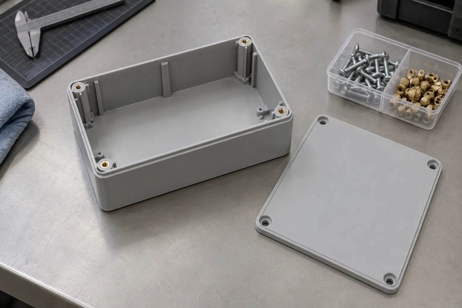
Start with how the cover will be serviced
A cover removed routinely for maintenance puts a different demand on its fastening points from a cover rarely opened. A metal insert gives the machine screw a metal mating thread, making it a useful candidate where preserving that interface through service matters. Direct fastening remains a credible option when a screw designed for the thermoplastic can meet the required removal and reassembly duty.
Define a service event as the actual removal procedure followed by the function the cover must recover. Record whether the technician reuses or replaces the screw, how access constrains alignment, and what the reinstalled joint must hold. A requirement to retain clamp under sustained load makes the behavior of the plastic important whichever thread route is chosen.
Use the expected maintenance schedule and failure consequences to prioritize candidates. Frequent intervention favors evaluating inserts early; infrequent, controlled opening favors trying direct screws where the boss and resin permit it. If the service duty is still undefined, keep the choice provisional rather than assuming that a removable cover requires metal threads.
Follow the load from the cover into the housing
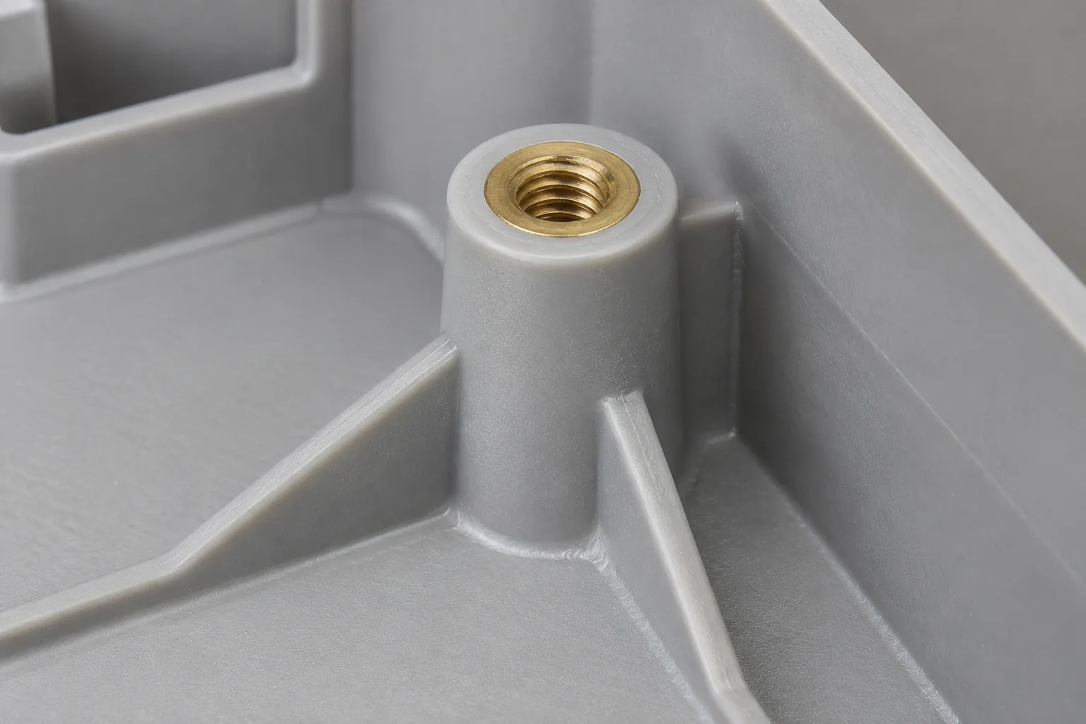
The screw head presses the cover against its seating surface. The screw then transfers load through either the insert's internal thread or the thread formed directly in the boss, the raised plastic feature around the fastening hole. The boss and its connection to the housing must carry that load into the surrounding walls and ribs.
A heat-installed insert is retained by plastic that flows around its external features and solidifies. The screw engages metal, but insert retention still relies on the molded material. A direct screw displaces plastic to form its mating thread; its geometry, engagement, and pilot hole affect the pressure applied to the boss. An ordinary machine screw or a tapped plastic hole is a different joint concept.
Plastic under sustained stress can gradually deform, a behavior called creep. If stressed plastic remains in the clamped stack, a metal thread alone does not stop clamp loss. Examine where the cover bears, whether it flexes, and how the boss joins the wall before assigning a loose cover to thread damage.
Check the assembled stack in the drawing and on a sample: head contact, seating surfaces, screw reach, and available hole depth. A screw that bottoms out can produce resistance at the driver without securing the cover. If that happens, correct the stack or fastener length before judging either fastening route.
Compare the features each route needs
Boss feasibility can reverse an early preference. An insert needs a hole and surrounding plastic suitable for its retention features and installation method. A direct screw needs its own resin-specific pilot hole and engagement. Neither design should inherit the other's dimensions merely because the cover uses the same fastening locations.
Review the exact resin formulation and filler with the molder and fastener supplier. Fillers change how material responds to installation and loading, so advice for another formulation is only a starting point. Include local walls, ribs, molded-hole consistency, and any weak knit line where melt fronts meet. Adding hardware does not repair poor molding quality.
| Decision dimension | Heat-installed insert and machine screw | Purpose-designed direct screw |
|---|---|---|
| Required component features | Insert-compatible cavity, supporting boss, and cover bearing relationship | Pilot hole and engagement matched to the selected plastic and screw |
| Manufacturing operations | Molding followed by controlled heating, insertion, and seating verification | Molding followed by direct thread formation during fastening |
| Assembly equipment | Insert installation fixture plus a controlled screw driver | Aligned driver with settings validated for forming and seating |
| Control points | Insert position, local plastic flow, cooling, and final screw engagement | Hole consistency, starting alignment, driving behavior, and clamp formation |
| Potential failure modes | Insert rotation or pull-out, boss cracking, and loss of clamp | Thread damage, split boss, incomplete seating, and reduced retention after service |
| Validation needs | Retention and assembled function after the intended maintenance exposure | Reusable joint behavior with the specified removal and reinstallation procedure |
Control installation without confusing torque with clamp
Heat installation adds a process between molding and cover assembly. Access must let the tool approach the boss squarely and support the part without distortion. Establish the heating, insertion, seating, and cooling method for the chosen material and insert. Visual seating checks help detect an obvious fault; retention testing and examination of installed samples address what surface appearance cannot establish.
SPIROL's heat-insert guidance ties performance to the hole, supporting plastic, and installation quality. Its hole-design guidance also addresses seating, mating clearance, and bottoming. Use these relationships to review the proposed joint with the supplier, rather than copying a generic boss ratio or installation setting.
For the direct route, distinguish torque spent forming the thread from torque used to seat and clamp the cover. Establish the usable assembly range on representative molded parts with the exact screw. EJOT's DELTA PT information describes a purpose-designed thermoplastic fastening route; product availability does not establish that a particular housing meets its service target.
Investigate abnormal driving resistance before increasing a setting. Misalignment, insufficient clearance, or an unsuitable hole can each make a driver work harder. Choose corrective action from the observed cause, then repeat the joint checks; a higher final torque reading is not proof of useful clamp.
Test maintenance and loading as a combined duty
An exploratory prototype can reveal an access problem or an obviously weak boss. Production selection needs evidence from the intended molded material, geometry, and installation route. Use the same cover function, loading, environmental exposure, and acceptance goal for both candidates, even if their approved assembly settings differ.
Record initial seating and joint condition, apply the specified service procedure and relevant load or temperature exposure, then assess the required post-service behavior. Observe cover movement, retained clamp where applicable, visible boss damage, thread condition, and insert movement. A joint that opens successfully but no longer holds the cover has not met the maintenance requirement.
Separate failure observations from explanations. A rotating insert points to its retention interface; a cracked boss prompts review of geometry, molding, and installation stress. A loose cover without those signs still warrants investigation of bearing surfaces and plastic deformation. Match the proposed fix to evidence and retest the complete assembly.
| Observed condition | Selection or correction action |
|---|---|
| Direct fastening meets service duty and retained-function criteria | Keep it in contention and compare delivery cost against a qualifying insert route |
| Plastic thread deteriorates during the required opening procedure | Review screw, pilot geometry, and service handling; evaluate an insert if thread durability remains limiting |
| Insert cannot be installed consistently or lacks local support | Revise its cavity, access, or installation process; reconsider direct fastening if the insert route remains impractical |
| Both concepts lose required clamp under exposure | Investigate the plastic bearing stack and load path before changing only the thread interface |
Compare the delivered joint, not just the hardware price
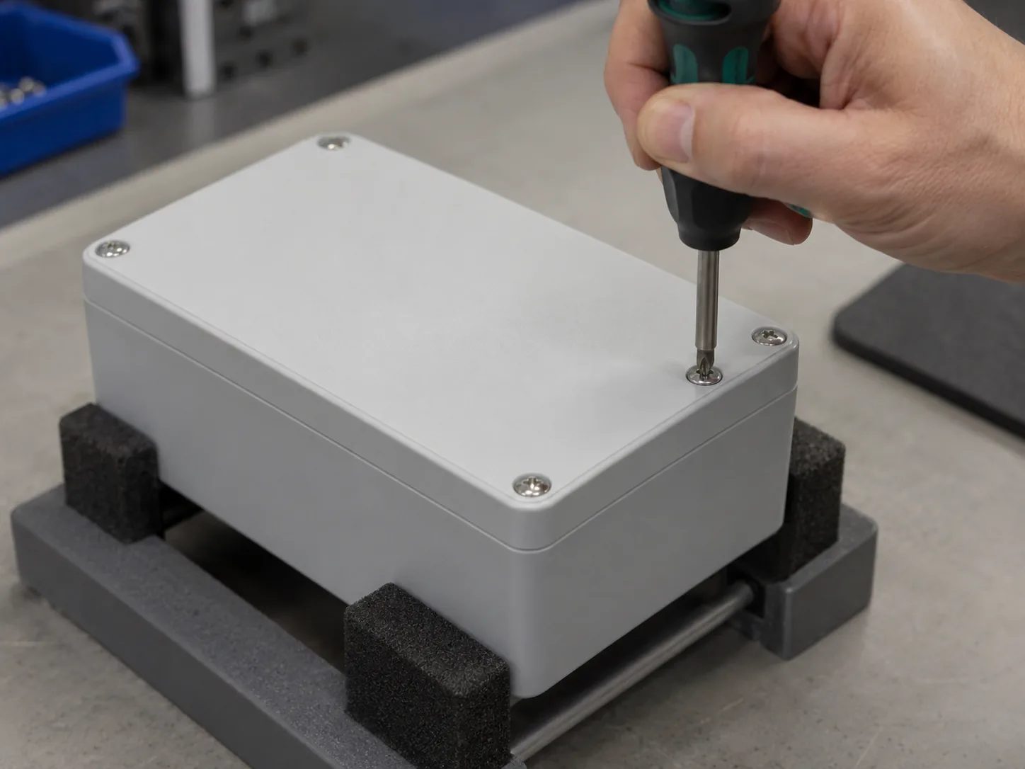
Direct fastening removes the separate insert installation step, which can be attractive for a small build with modest service demands. It still needs appropriate screws, driver controls, inspection, and qualification. The insert route adds purchased components, installation equipment or labor, fixtures, checks, and scheduling between molding and final assembly.
Recurring orders can spread fixture and process-development effort over more assemblies. They also make consistent output and capacity more consequential. Request costs at the stated annual and lot quantities, with tooling assumptions and manufacturing responsibilities visible. An insert may justify its extra operation through the required service interface, but no universal cost saving follows.
When both options pass the joint requirements, compare complete delivery terms: validation work, downstream assembly, inspection, corrective processing, maintenance hardware, lead time, and supply responsibility. If a route fails, include the redesign and retesting implications before treating its apparent price advantage as a production option.
Prepare an RFQ that can resolve the remaining choice
Send a package that lets a supplier evaluate the joint rather than quote disconnected hardware. Ask each bidder to identify the proposed manufacturing route, what it will verify, and which acceptance requirements remain unresolved. This makes an insert installation quote comparable with a direct-fastening proposal.
- Provide housing CAD and drawings showing the boss, nearby walls and ribs, cover stack, clearances, and cosmetic limits.
- Identify the exact resin formulation and filler, along with relevant material information for the intended environment.
- Name the proposed insert and compatible machine screw, or the direct screw candidate, with thread size and intended engagement.
- Describe the required loads, clamp behavior, operating temperature, and acceptance criteria after maintenance.
- Explain removal events, the service tool and access path, and the procedure for reusing or replacing fasteners.
- State assembly-control expectations and available observations from prototype or molded-sample checks.
- Give annual and lot quantities, tooling assumptions, quality responsibilities, and target delivery.
Make the choice conditional on the joint evidence
Select the insert route when protecting a repeatedly used service thread is important, the installation can be controlled, and the molded support passes the required duty. Select direct fastening when its resin-specific design demonstrates acceptable reassembly and cover function, and the simpler manufacturing route offers suitable delivery terms.
Bring the joint drawings, material identification, maintenance procedure, and any damage or assembly observations to the quotation review. With these inputs, the supplier can identify feasible boss changes and propose a testable installation route. Commit to production after the remaining service and load evidence supports the chosen assembly, rather than using catalog performance as the housing's result.
Frequently asked questions
Can a field technician replace a lost screw with a similar-looking one?
Treat a substitute as a joint change. For direct fastening, thread geometry determines how the replacement interacts with the existing plastic thread. For an insert, machine-screw compatibility still includes length, head contact, and clearance. Specify approved replacement hardware in the service instructions.
Does changing the resin supplier require another fastening review?
A change in formulation or filler can alter installation behavior and local strength even if the enclosure looks unchanged. Compare the material specification and assess which installation and service tests must be repeated before accepting the change.
Can a cracked boss be repaired by fitting an insert?
Existing damage removes confidence in the supporting plastic. An insert needs sound material around its retention features, so retrofitting hardware is not an established repair. Decide whether to replace the housing or develop a qualified repair using the actual damage and load requirements.
Who should own the verification when molding and assembly are outsourced separately?
Assign responsibility for the finished joint's acceptance, not just each supplier's operation. The molder supplies the agreed material and geometry; the installer or assembler controls its process. The product owner needs traceable evidence that the resulting cover assembly meets the maintenance requirement.