
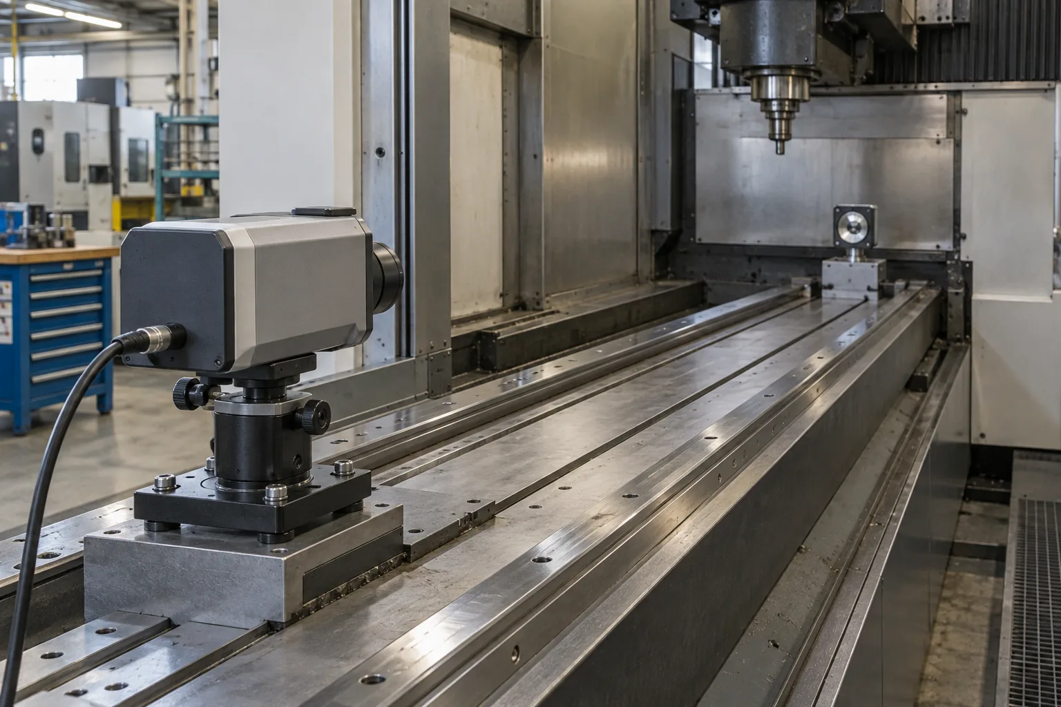
What changed—and what the specification means
The Renishaw XC100 environmental compensator, introduced in the September 2026 launch announcement, works with XL-80, XM-60 and XM-600 systems and CARTO. Flexible combinations of air and material sensors help adapt coverage to the calibration setup.
The stated accuracy concerns linear laser measurement. Total uncertainty also reflects how the equipment is positioned, how the machine behaves and how the procedure is performed. Compatibility offers an adoption route for existing users, rather than proof that an upgrade will meet their acceptance criteria.
Why air and material temperatures need different corrections
A laser uses its wavelength as a measuring scale. Air temperature, pressure and humidity affect that scale, so the XC100 monitors them for real-time wavelength correction. Changing conditions can otherwise influence the reported distance.
Machine material expands or contracts as its temperature changes. Material-temperature readings support normalization to a common reference temperature. This is a separate correction: an air reading cannot establish the temperature of the machine structure, and a contact sensor describes its location rather than every region of the machine.
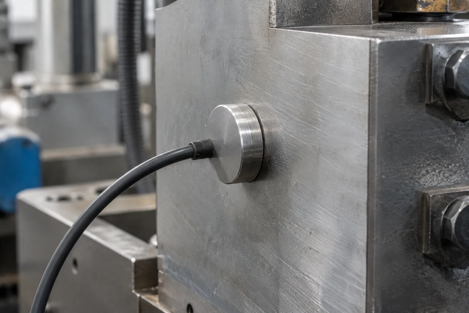
Where an upgrade is likely to matter
For long travel in a variable environment, a scale-related error has more distance over which to accumulate. Better environmental measurement is therefore worth evaluating when that contribution consumes a significant share of the allowable uncertainty. A stable room may offer less benefit if other contributors already set the limit.
| Calibration condition | Likely priority | Decision evidence |
|---|---|---|
| Long travel with changing surroundings | Evaluate compensation and representative sensor coverage | Environmental contribution remains significant after setup and machine-state checks |
| Stable room; alignment or repeatability limits the result | Correct geometry or stabilize the machine first | Trials identify a larger contributor outside environmental sensing |
| Different temperatures across the structure | Investigate gradients and revise sensing locations | Local readings and repeat measurements explain whether normalization is representative |
Review coverage before choosing equipment
Map the air path and relevant material locations during the intended machine state. Look for nearby heat sources, drafts and areas that warm differently. A sensor placed somewhere convenient may miss the conditions that affect the measured axis.
Use the findings to revise the uncertainty budget. Adding sensing locations helps only when their readings represent the affected region and the procedure uses them appropriately.
- Define the axis, travel and acceptance target for the calibration.
- Check sensor calibration records and their traceability.
- Locate air sensing where it represents the measurement path.
- Establish reliable material-sensor contact at relevant structural locations.
- Record environmental changes alongside machine warm-up and motion.
- Allocate uncertainty to compensation, alignment, repeatability and procedure.
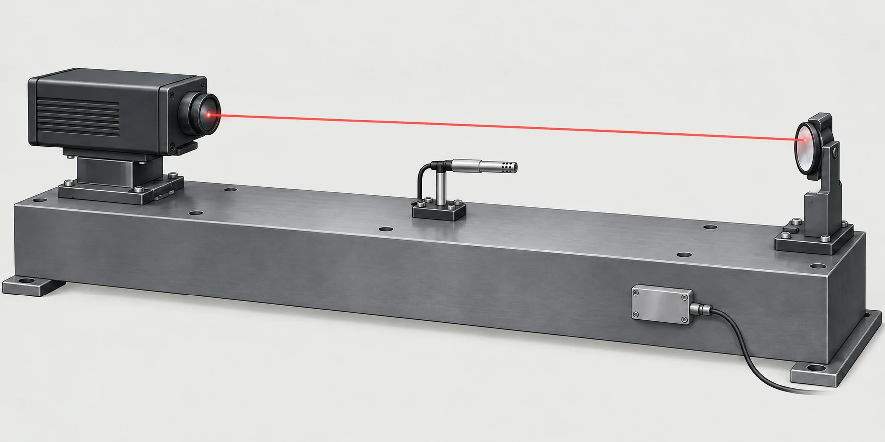
Validate the choice under matched conditions
Evaluate the existing arrangement and proposed upgrade for the same axes, operating state, environment and acceptance goal. Examine the combined uncertainty and repeatability, rather than selecting whichever trial gives the smallest correction.
If the target is missed, use the dominant contributor to choose between revised placement, better thermal stability, setup correction or a different calibration approach. After acceptance, compare the complete delivery conditions: verification work, sensor maintenance, reporting and downtime. A numerical XC-80 comparison needs verified product documentation.
Neither compensation nor a successful calibration establishes that manufactured parts meet tolerance. Geometry, unrepresented thermal gradients and unsuitable procedures remain possible limits; machine warm-up and maintenance still matter.
Prepare a calibration request that supports a decision
Provide the machine type, travel, axes, desired uncertainty and acceptance criteria. Include ambient observations, material-temperature locations, proposed sensor coverage, installed hardware and software, traceability needs, the applicable calibration standard and reporting format.
Add access restrictions and the available downtime window. With those inputs, a provider can assess whether better environmental sensing addresses the limiting contribution, propose a representative setup and identify which validation work is needed before purchase.
Frequently asked questions
Why might a quiet trial fail to predict calibration during normal production?
A trial taken before nearby equipment warms up may not represent later air movement or structural temperature patterns. Repeat the assessment during the intended operating state before treating the trial as evidence of usable uncertainty.
Does choosing a compatible system mean existing sensors can be reused?
System compatibility does not establish the suitability of each accessory. Verify sensor support, calibration status and installation requirements in the product documentation and proposed configuration.
What evidence supports attributing a result change to compensation?
Retain time-aligned environmental records and repeated measurements with setup and machine state controlled. A changed result without that context may also reflect alignment, drift or motion behavior.