
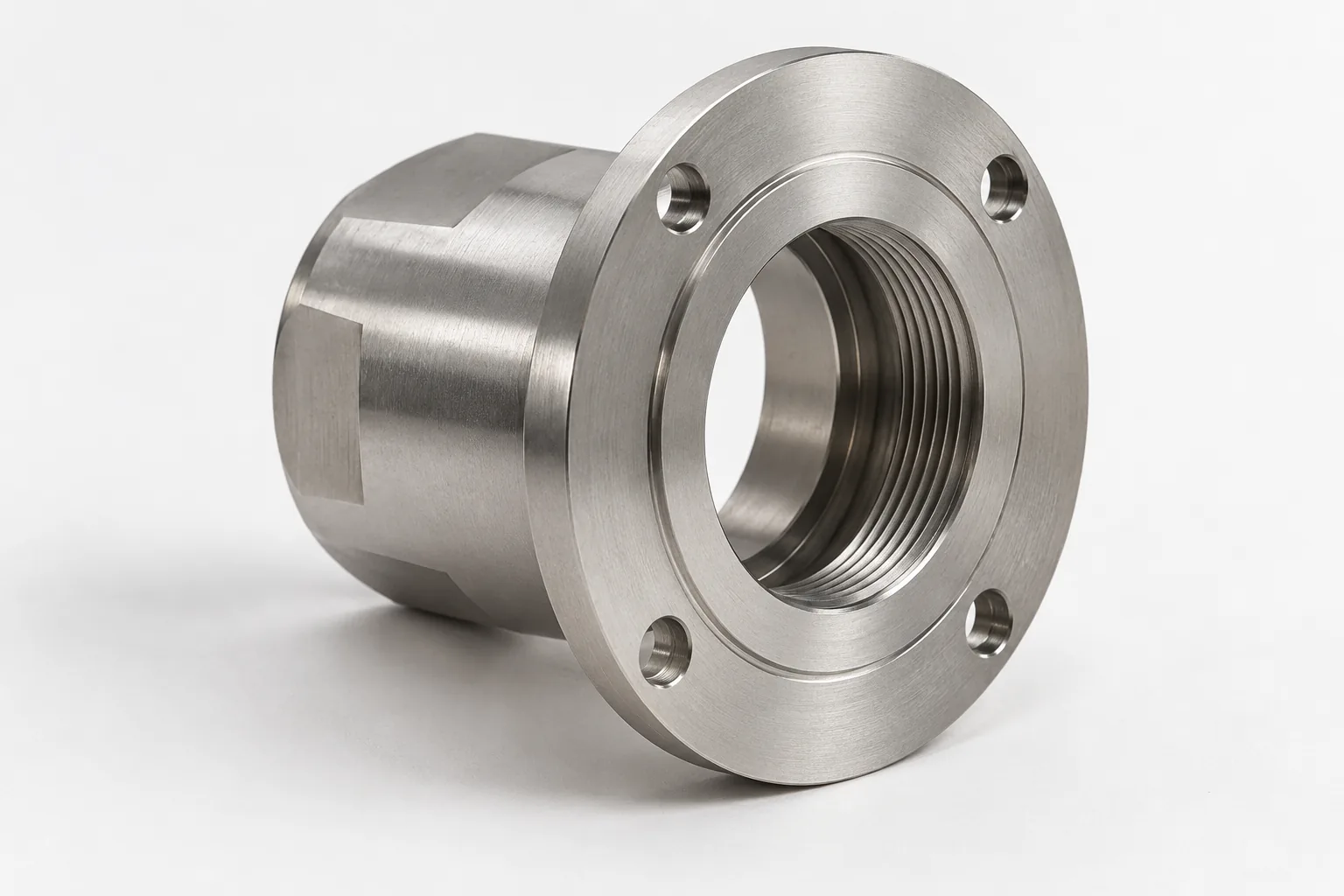
Project overview
Machine-vision inspection systems
Precision lens mount
Prototype or low-volume production planning; actual stage must be supplied from real project data
CNC turning and milling of a 17-4 PH stainless steel lens mount for machine-vision inspection equipment, centered on maintaining the relationship among optical bore, seating face, thread, and mounting features across setups
What this case documents—and what it does not
Public evidence
No actual customer-project evidence was supplied; the sector, component, 17-4 PH material, CNC route, and concentricity challenge are editorial premises
Confirm from customer files
CAD, material condition, critical datums, bore and thread requirements, finish, quantity, inspection method, acceptance data, and project outcome must be confirmed from authorized files
The four anchors define a coherent editorial topic but do not prove a completed customer project; all exact performance and outcome statements require approved evidence
Engineering focus
Common-axis feature strategy—explain why bore, seating face, and thread relationships may favor same-holding or datum-preserving operations
Setup-transfer control—show how locating surfaces and soft-jaw or fixture concepts can protect critical relationships during secondary milling
Stainless finishing and edge control—connect tool access, burr management, surface specification, heat treatment, and passivation to functional interfaces
Lens mount context and evidence boundary
The mount positions a lens assembly relative to the camera and machine structure. Stainless steel lens mount CNC machining combines turning for axis-related features with milling for mounting details. Re-clamping can shift or tilt the workpiece reference, changing how later features relate to the optical bore.
This is a manufacturing-planning guide, not a completed customer case. The application, material, route, and challenge are editorial premises; actual stage, geometry, requirements, and outcomes depend on authorized project files.
| Planning parameter | Basis |
|---|---|
| Component | Machine-vision lens mount |
| Route | CNC turning and secondary milling |
| Material | 17-4 PH stainless steel |
| Project-specific specifications | Customer files must supply condition, geometry, finish, quantity, and acceptance requirements |
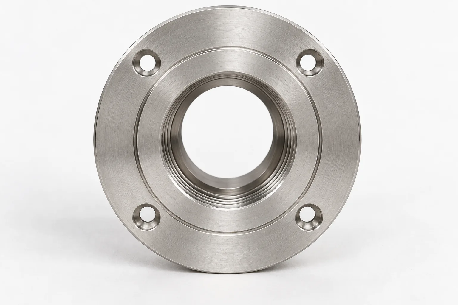
Engineering focus: common-axis features
Finish the bore, seat, and related thread together when tool access allows. Their shared holding reduces opportunities to introduce another alignment error. The seating face also sets axial support; a bore with acceptable diameter does not establish the seat relationship or assembled optical alignment.
Where access forces separation, identify the locating feature before choosing the sequence. Compare the proposed datum with the drawing’s functional reference and check the resulting relationship after transfer.
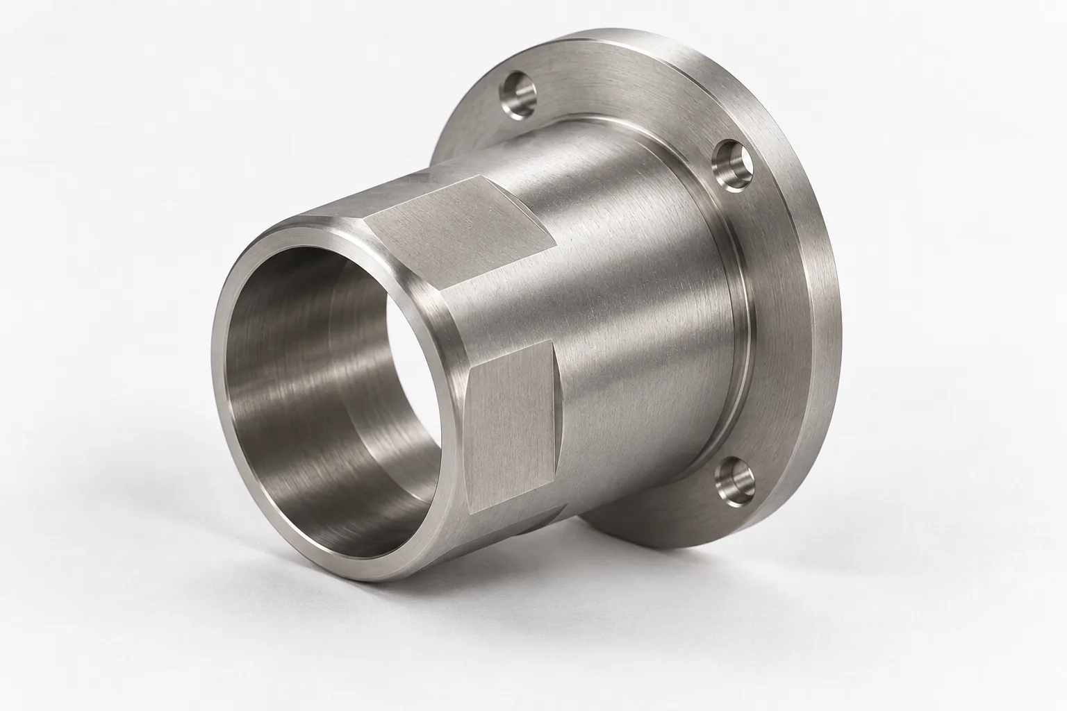
Engineering focus: preserving references during transfer
A locating surface controls where the part sits; a supporting face helps control its tilt. Soft jaws or a dedicated fixture are candidates only when they engage suitable references without distorting the mount. Chips or burrs under a contact can prevent full seating.
When re-clamping leaves the mounting features displaced relative to the optical bore, re-seat a trial part and compare their relationship using the same reference method.
If the offset remains consistent after repeated re-clamping, check the locating reference against the functional datum and whether re-location reproduces the same positioning error.
If the displacement changes when the part is re-seated, examine contact surfaces for chips or burrs, then check support and clamping stability.
These observations direct the investigation without proving a root cause; consider changing the bore toolpath only after the transfer positioning factors have a reasonable explanation.
Engineering focus: stainless finishing and edges
The specified 17-4 PH condition affects machining and finishing decisions; the alloy name alone does not define the delivered state. Confirm heat treatment and passivation requirements before fixing the final sequence.
Burrs at a seat or thread entry can obstruct mating even when primary surfaces are acceptable. Plan tool access and controlled edge finishing around those interfaces. If approved post-processing follows final cutting, assess which characteristics need another check afterward.
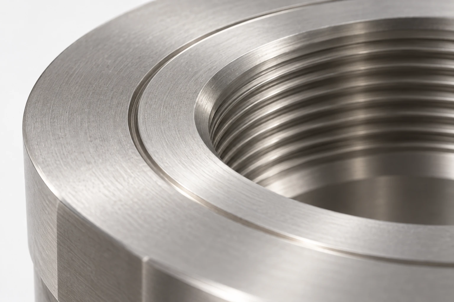
A linked machining plan
Establish references that can carry forward from turning into the milling of mounting features. The confirmed material condition informs the finishing sequence, while any approved treatment after cutting determines which interfaces must be reassessed before final acceptance.
- Review the drawing and identify functional datums.
- Confirm material condition and suitable stock.
- Turn primary features and create transfer references.
- Choose the finishing sequence for bore, face, and thread.
- Locate from preserved datums to mill mounting features.
- Deburr and apply approved post-processing.
- Verify dimensions and functional-interface relationships.
Quality checks tied to function
A coordinate measuring machine (CMM) can assess datum-based relationships. Rotating runout observations can combine effects from form, centering, and tilt; interpret them against the drawing rather than treating them as interchangeable with every geometric requirement.
| Feature | Control intent | Typical verification |
|---|---|---|
| Optical bore | Size and axis relationship | Calibrated bore measurement; datum-based CMM assessment |
| Seating face | Axial position and orientation | Face assessment referenced to the specified axis |
| Thread | Mating engagement and position | Specified thread gauges; relationship checks |
| Mounting pattern | Location relative to optical interface | CMM assessment from functional datums |
| External reference | Reliable transfer contact | Surface inspection and seating checks |
| Edges | Unobstructed assembly and handling | Visual examination of specified edge condition |
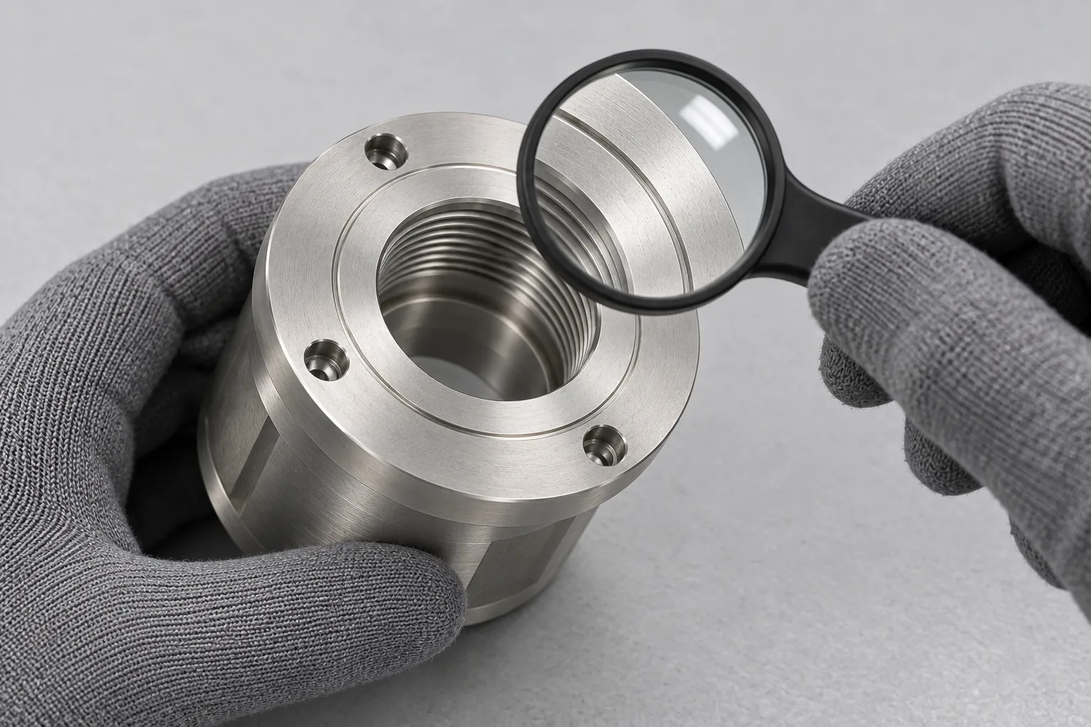
Prepare an RFQ that resolves the machining decisions
Start a CNC quote by uploading the CAD and datum-controlled drawing. Include the material condition, heat treatment, bore and thread requirements, geometric tolerances, roughness, passivation, quantity, cleanliness, and target lead time.
Provide mating-interface information and reporting needs as well. These inputs let the supplier choose viable holdings and verification methods, then identify unresolved access or finishing risks before quoting.
Process planning
- Present 7 linked steps: drawing and datum review
- material-condition and stock confirmation
- primary turning and reference creation
- bore, face, and thread finishing strategy
- datum-preserving transfer for milled mounting features
- deburring and approved post-processing
- final dimensional and functional-interface verification. Avoid asserting a specific shop executed these steps
Quality control
| Feature / control / verification |
|---|
| Use Feature | Control Intent | Typical Verification for optical bore, seating face, thread, mounting pattern, external reference, and edge condition. Explain candidate use of calibrated bore measurement, runout assessment, CMM, thread gauges, and surface inspection without inventing values |
Prepare your RFQ
3D CAD, datum-controlled 2D drawing, 17-4 PH condition, heat treatment, bore and thread specifications, geometric tolerances, surface roughness, passivation, quantity, mating optics, inspection reporting needs, cleanliness, and target lead time
Documented outcome and verification boundary
Publish only customer-approved manufacturing and inspection evidence; no current data confirms tolerance achievement, optical alignment, surface result, batch capability, or lead time
Do not claim zero runout, guaranteed concentricity, perfect optical alignment, universal precision capability, fixed price, or guaranteed delivery
Outcome and verification boundary
A suitable plan connects machining references to assembly function. Publish achieved results only when customer-approved manufacturing and inspection records support them. No available project evidence confirms tolerance achievement, optical performance, surface result, batch capability, cost, or delivery.
Frequently asked questions
Does a thread gauge confirm that the lens is centered?
It checks the specified thread fit. Centering depends on which mating surfaces locate the lens and their relationship to the bore; establish that interface before selecting alignment checks.
Should every external surface become a locating datum?
Use surfaces that represent function and can seat reliably. A convenient outer surface may be unsuitable if its relationship to the optical interface is unspecified.
What should change when dimensional checks pass but assembly is unstable?
Review mating contacts, cleanliness, and edge interference before attributing the behavior to machining accuracy. Compare the assembly observation with the acceptance requirement and choose a focused verification.