
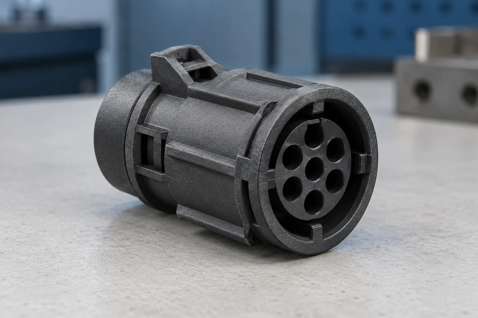
Project overview
Industrial automation connectivity
Circular connector housing
To be supplied from real project data
An industrial automation circular connector housing in PA66-GF30 made by injection molding, with warpage and terminal-cavity alignment as the central engineering challenge
What this case documents—and what it does not
Public evidence
No actual project evidence was supplied; industry, component, material, process, and challenge are editorial premises
Confirm from customer files
Connector standard, resin specification, terminal map, sealing features, dimensions, tolerances, mold ownership, volume, validation scope, and outcome—To be supplied from real project data
The four anchors and core challenge define the planned topic, not a verified customer program. Mark all unavailable exact facts To be supplied from real project data and keep the evidence module prominent
Engineering focus
Circular interface stability—explain how wall transitions, ribs, and cooling symmetry influence mating geometry
Terminal-cavity core alignment—show how slender or grouped cores require support and an inspection strategy tied to functional datums
Fiber-orientation-aware filling—connect gate and flow direction to anisotropic shrinkage without claiming an unverified optimal gate
Why the circular mating rim can lose its shape
A connector housing can look acceptable on the bench yet resist mating if its rim becomes oval or tilts relative to the terminal pattern. In PA66-GF30 connector housing injection molding, glass fibers can restrain shrinkage differently along and across their direction. Flow around the housing therefore matters to the shape that remains after cooling.
Local thick sections cool more slowly than adjoining thin walls. When a rib joins the rim through an abrupt thickness change, the surrounding material can contract unevenly and pull the interface away from its intended geometry. Uneven cooling can add to that movement. These are plausible mechanisms, not an established diagnosis for a supplied part.
Review wall transitions and rib attachment points in the CAD, then map measured rim departures to those locations and the expected flow path. If distortion tracks a heavy junction, smoothing that transition deserves evaluation. A broad directional pattern instead calls for a closer look at filling and cooling. Neither pattern alone identifies the cause.
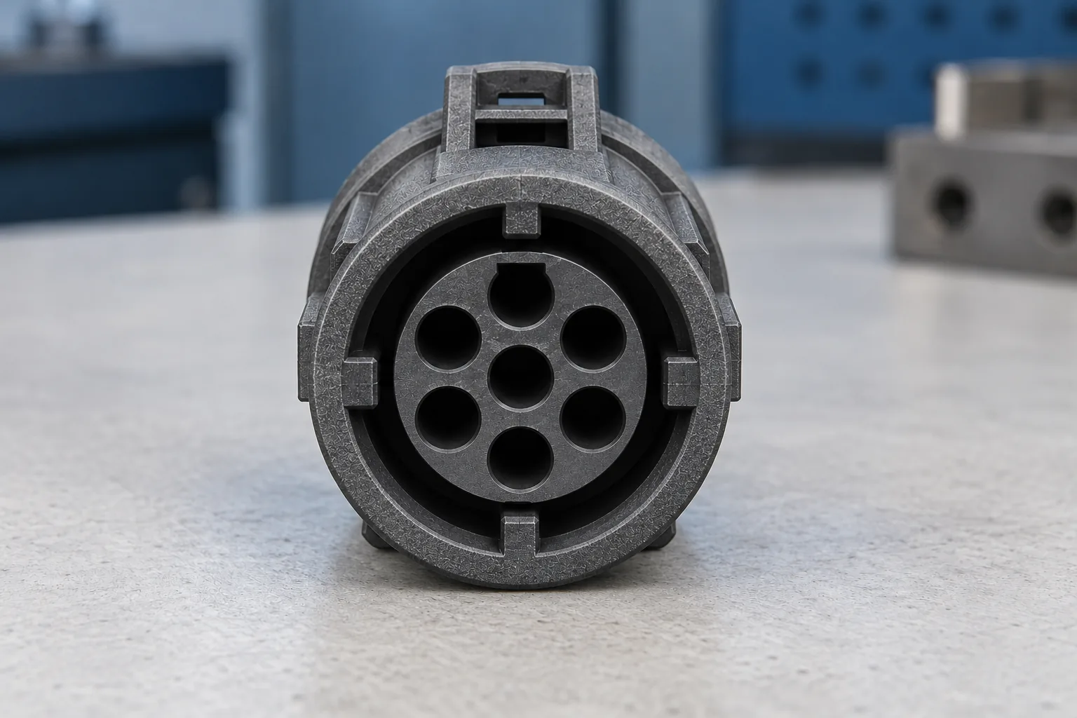
Keep terminal cavities tied to the mating datums
The rim and the terminal openings have to locate from the same functional reference. A housing may preserve its overall circular outline while an opening moves relative to the mating interface. Checking appearance alone would miss that assembly risk.
Slender cavity-forming cores can bend under molding pressure; grouped cores also depend on their support and relative tool position. Local shrinkage around the openings offers another route to displacement. The tooling review should distinguish movement of a core from movement of the polymer around it.
Locate each cavity from the drawing's mating datums rather than aligning an inspection solely to the hole pattern. Where an offset persists in a consistent direction, examine core seating and support alongside the corresponding tool geometry. Where the pattern changes with documented molding conditions, investigate flow and cooling before committing to steel changes.
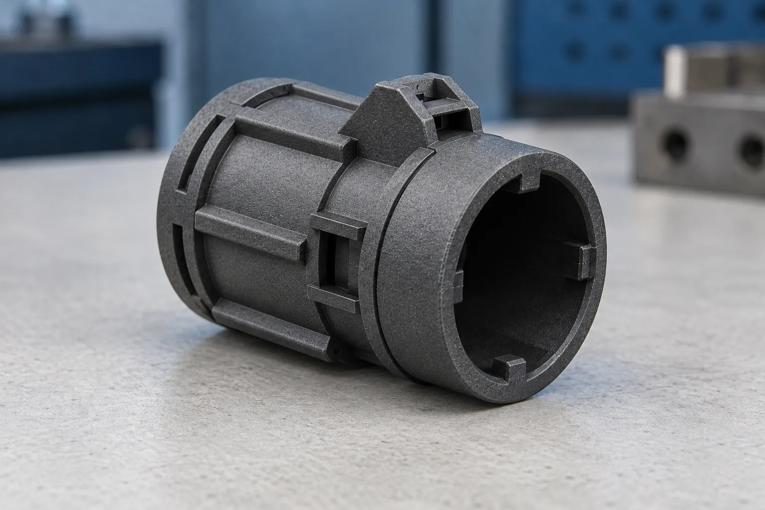
Choose filling and cooling hypotheses that match the geometry
A balanced fill is a starting hypothesis for the circular housing, not permission to declare a universal gate position. Gate location changes the melt path, fiber direction and where flows meet around cavity-forming features. An apparently symmetric layout can still produce uneven local flow around ribs or openings.
If the flow analysis points to competing shrinkage directions around the rim, compare practical gate alternatives using the same resin, geometry and acceptance objective. If cavity displacement is associated with insufficient core support, changing the gate alone may leave the mechanical weakness unresolved.
Cooling should support a consistent thermal history around the interface and adjoining features. Compare samples under recorded process and conditioning states. A route that improves roundness but compromises cavity position, latch function or the drawing-defined seal interface needs adjustment and renewed evaluation.
A sampling plan that connects changes to observations
The proposed work begins with the interfaces the customer needs to assemble. Sampling then tests a limited set of tooling and process hypotheses, so an observed change can be related to an intentional intervention.
- Review approved CAD, drawings and resin requirements; identify the mating reference and terminal interface before setting measurement priorities.
- Examine walls, ribs, draft and core access in DFM; flag abrupt sections or unsupported features for a specific tooling discussion.
- Define gate, venting, core-support and cooling options; record what each option is expected to change and what observation would challenge it.
- Build and sample the tool under documented conditions; keep material preparation and sample conditioning traceable.
- Measure the rim and cavity relationships; correct the feature or condition supported by the evidence, then repeat the affected assembly checks.
- Evaluate finishing and ongoing process controls against customer criteria; retain an unsuccessful trial as evidence for adjustment rather than declaring completion.
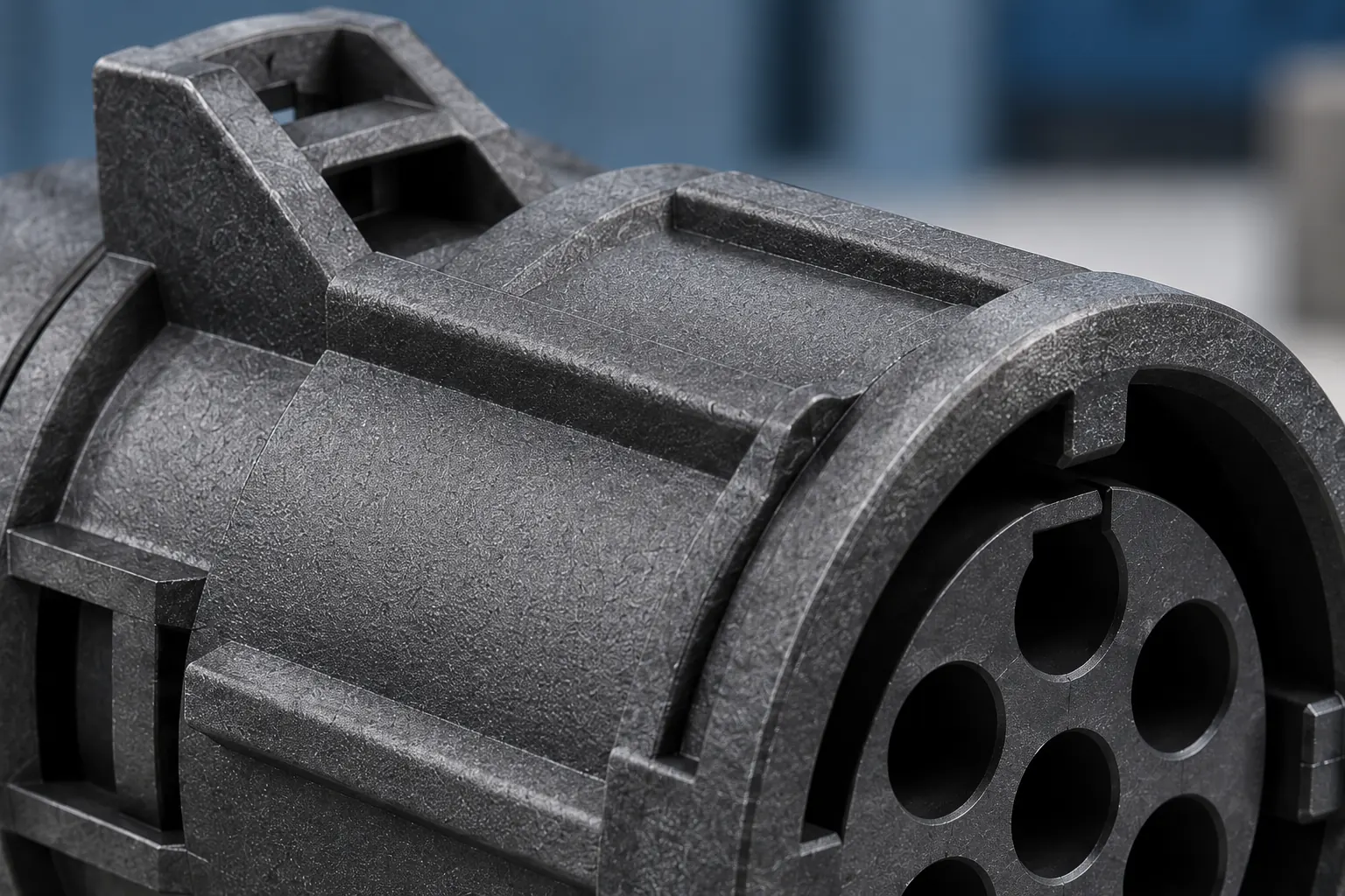
Verify shape and assembly as separate questions
Dimensional inspection describes the housing geometry. Functional checks ask whether that geometry works with the specified mating, terminal and seal interfaces. Passing either kind of check does not automatically establish the other.
Use the agreed sample condition and reference system for comparisons. If geometry falls outside the drawing, investigate and resample the affected features. If dimensions satisfy the drawing but assembly remains problematic, review the mating components, tolerance relationships and test setup before attributing the problem to molding alone.
| Feature | Control intent | Typical verification |
|---|---|---|
| Circular mating interface | Preserve the required shape and orientation to the functional reference. | Drawing-based rim measurements and a fit check with the specified mating interface. |
| Terminal cavities | Maintain opening positions and orientation relative to the connection interface. | Datum-referenced metrology plus checks using the approved terminal arrangement. |
| Sealing features | Protect the drawing-defined sealing geometry when such features are specified. | Feature inspection and the customer's relevant functional test; a visual check does not establish ingress performance. |
| Latch and edge condition | Support engagement and avoid flash or damage at functional edges. | Visual examination and an agreed engagement check without assuming an unpublished acceptance result. |

Evidence boundary and information still required
The application, circular housing, PA66-GF30 and injection molding define this planned topic for industrial automation connectivity. They do not document a customer program. Project stage, quantity, exact dimensions and tolerances, finish, color, moisture condition, mold specification, post-processing and schedule: To be supplied from real project data.
The resin designation, connector standard, terminal map, seal requirements, approved part and tool files, mold ownership and configuration, process window, validation scope, metrology, assembly records and authorized outcome are also needed before project-specific conclusions. Their availability will determine which tooling decisions and acceptance statements can be supported.
No sampling result is presented here. A publishable outcome would identify the tested features, relevant conditions, customer criteria and recorded result. Electrical ratings, certification, yield, cycle time, tooling steel, shrinkage values, price and lead time cannot be inferred from the material name or component category.
Process planning
- 1. Review CAD, drawing, resin requirements, and functional interfaces. 2. Perform DFM on walls, ribs, draft, and core accessibility. 3. Define gate, venting, core support, and cooling hypotheses for validation. 4. Build and sample the tool under documented conditions. 5. Measure mating geometry and cavity relationships, then make evidence-based corrections. 6. Approve finishing and production controls only against customer criteria
Quality control
| Feature / control / verification |
|---|
| Present a Feature | Control Intent | Typical Verification table for the circular mating interface, terminal cavities, sealing features, and latch/edge condition |
| distinguish dimensional metrology and functional checks from actual unpublished acceptance results |
Prepare your RFQ
3D CAD, 2D drawing, resin and color, annual and batch quantity, terminal and seal interfaces, critical dimensions, cosmetic requirements, applicable standards, validation plan, packaging, and target timing
Documented outcome and verification boundary
Describe only supported sampling and validation evidence. Do not state that warpage, sealing, electrical, or assembly requirements were achieved unless records authorize publication
Guaranteed zero warpage, universal shrinkage compensation, certified ingress protection, perfect cavity alignment, fixed tool life, fixed price, or fixed lead time
Prepare the RFQ to make the tooling decision useful
Supply the native part model and drawing together with the resin and color requirements, expected annual and batch volumes, terminal and seal interfaces, critical features, cosmetic expectations, applicable standards and validation plan. Include packaging and target timing so the proposed delivery covers more than a molded sample.
Configure a quote with those files and identify which interfaces are still provisional. A project discussion can then separate geometry changes from tooling support and process trials, define what the samples must demonstrate, and compare delivery conditions including validation, finishing and maintenance. Feasibility for a similar housing depends on verified interfaces and agreed acceptance criteria.
Frequently asked questions
Should trial samples be compared immediately after molding?
Specify the comparison state first. Nylon's moisture condition can influence dimensions, so samples evaluated at different conditioning states may suggest a process effect that is actually a material-state difference. Obtain the customer's conditioning requirement before interpreting a trend.
When is increasing packing pressure an inadequate correction?
If a thin core lacks support or a rib junction drives uneven contraction, extra pressure does not remove that underlying feature. It may also change the load on cores. Test a targeted hypothesis and inspect all affected functional relationships rather than treating pressure as a general cure.
What would make a tooling-change recommendation credible?
A recommendation needs a reproducible mismatch, its location relative to the approved reference geometry, and trials that discriminate between plausible causes. Preserve the baseline tool condition and sample history; that allows a proposed modification to be assessed without confusing it with an unrelated material or process change.