
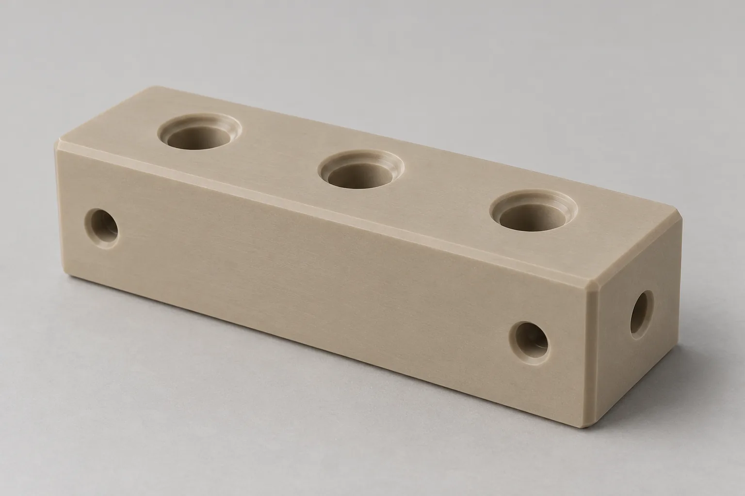
Project overview
Laboratory diagnostics equipment
Reagent distribution manifold
To be supplied from real project data
A laboratory diagnostics PEEK reagent distribution manifold produced by CNC machining, centered on controlling intersecting internal channels and burr-sensitive sealing faces
What this case documents—and what it does not
Public evidence
No customer project facts were provided; the diagnostics application, manifold, PEEK material, CNC process, and stated challenge are planning anchors
Confirm from customer files
Fluid map, port specifications, exact PEEK grade, sealing geometry, tolerances, cleaning protocol, quantity, and test criteria—To be supplied from real project data
The application, component, PEEK, and CNC machining are editorial premises. Every other exact unprovided project fact must read To be supplied from real project data, with documented facts visibly separated from file-confirmed and prohibited information
Engineering focus
Channel-intersection sequence—explain how drilling order and accessible breakout locations affect burr-removal strategy
Polymer workholding and thermal control—show why restrained clamping and cutting heat matter to broad sealing surfaces
Sealing-land protection—connect toolpath, handling, and inspection to the drawing-defined interface rather than generic precision claims
Application and the information needed to define the part
The proposed diagnostics manifold routes reagents through a compact PEEK body using CNC milling and drilling; it is not a delivered customer case.
Stage, grade, dimensions, tolerances, finish and quantity: To be supplied from real project data. Obtain approved channel connections and seal geometry before selecting operations.
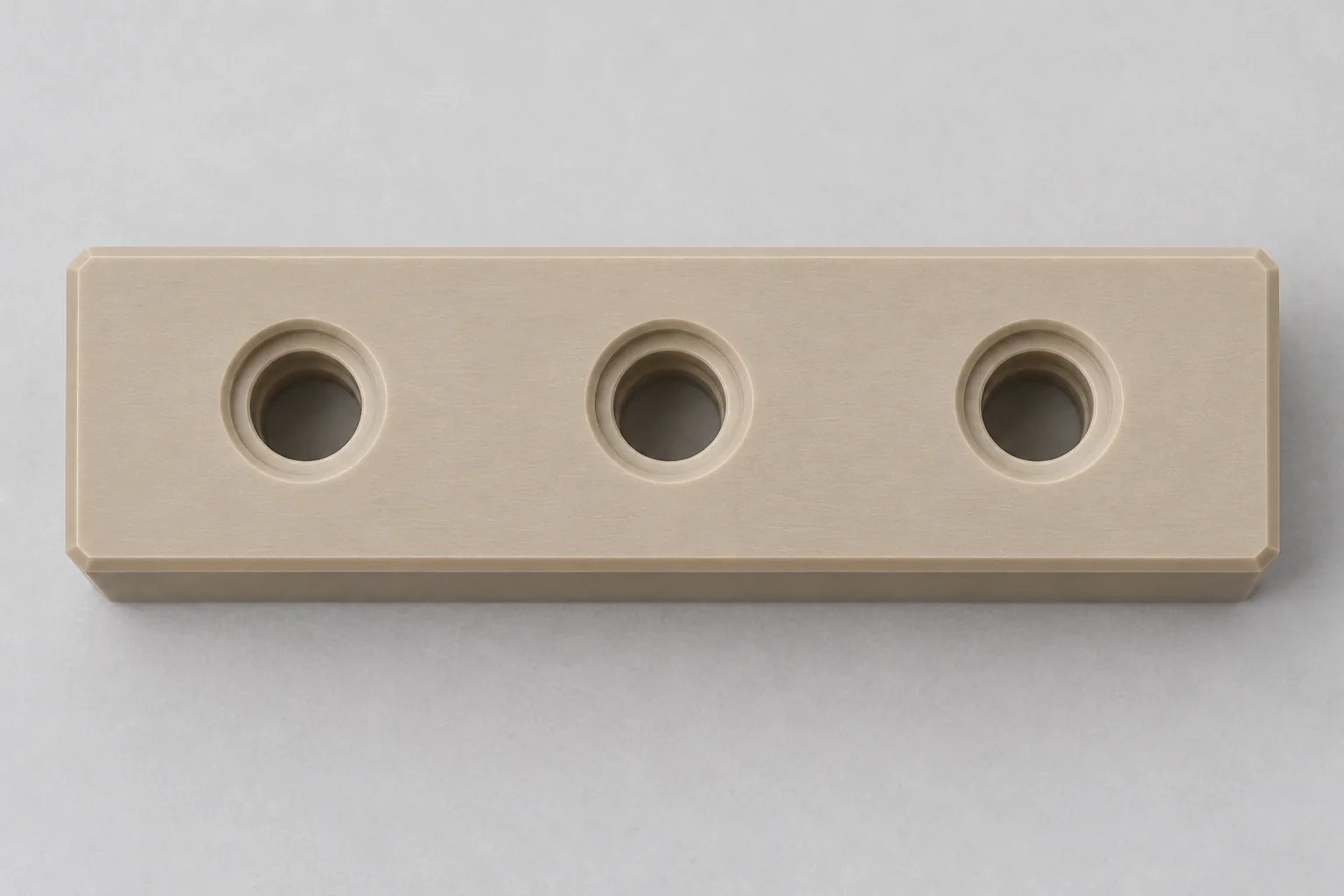
Choose channel order around reachable breakthrough edges
Drilling into another passage can leave a junction lip beyond an entrance tool's reach; a tidy port mouth does not establish internal condition.
Treat reachable edges before a cut or setup removes access, and address fresh breakthroughs. Another passage does not inherently block access; unresolved reach requires customer review.
Trace tool approach on the flow map, avoiding sealing lands and inward debris. Agree verification for concealed junctions.
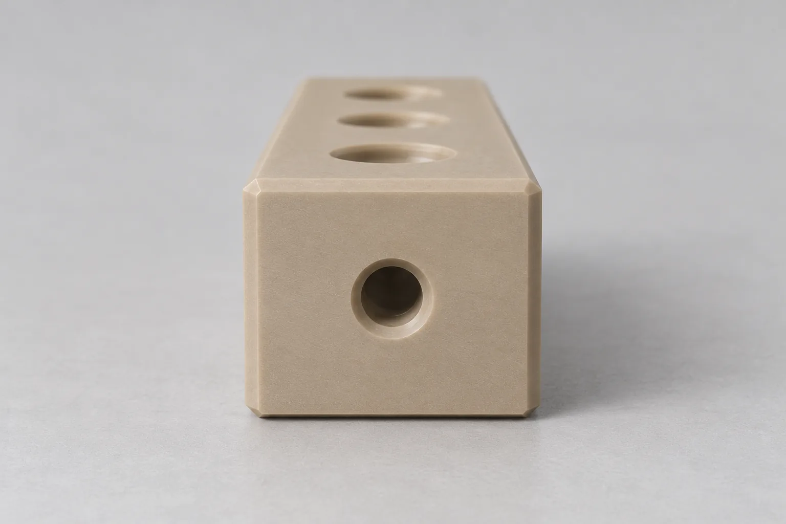
Support the polymer without hiding movement at the sealing face
Clamping and cutting heat can distort PEEK; a face machined flat may move after release or cooling.
Favor distributed support and restrained pressure; confirm sharpness, chip evacuation and thermal control against grade and geometry.
Inspect in the specified unloaded condition. Resolve movement before recutting; further finishing alone may not correct its cause.
Finish and protect the interface defined by the seal
Burrs or handling marks can interrupt seal contact; significance depends on the specified mating interface.
Finish lands after channel and edge work where access and datums permit; otherwise protect and reinspect them.
Check mating geometry and edge requirements before removing marks, which could round a required edge.
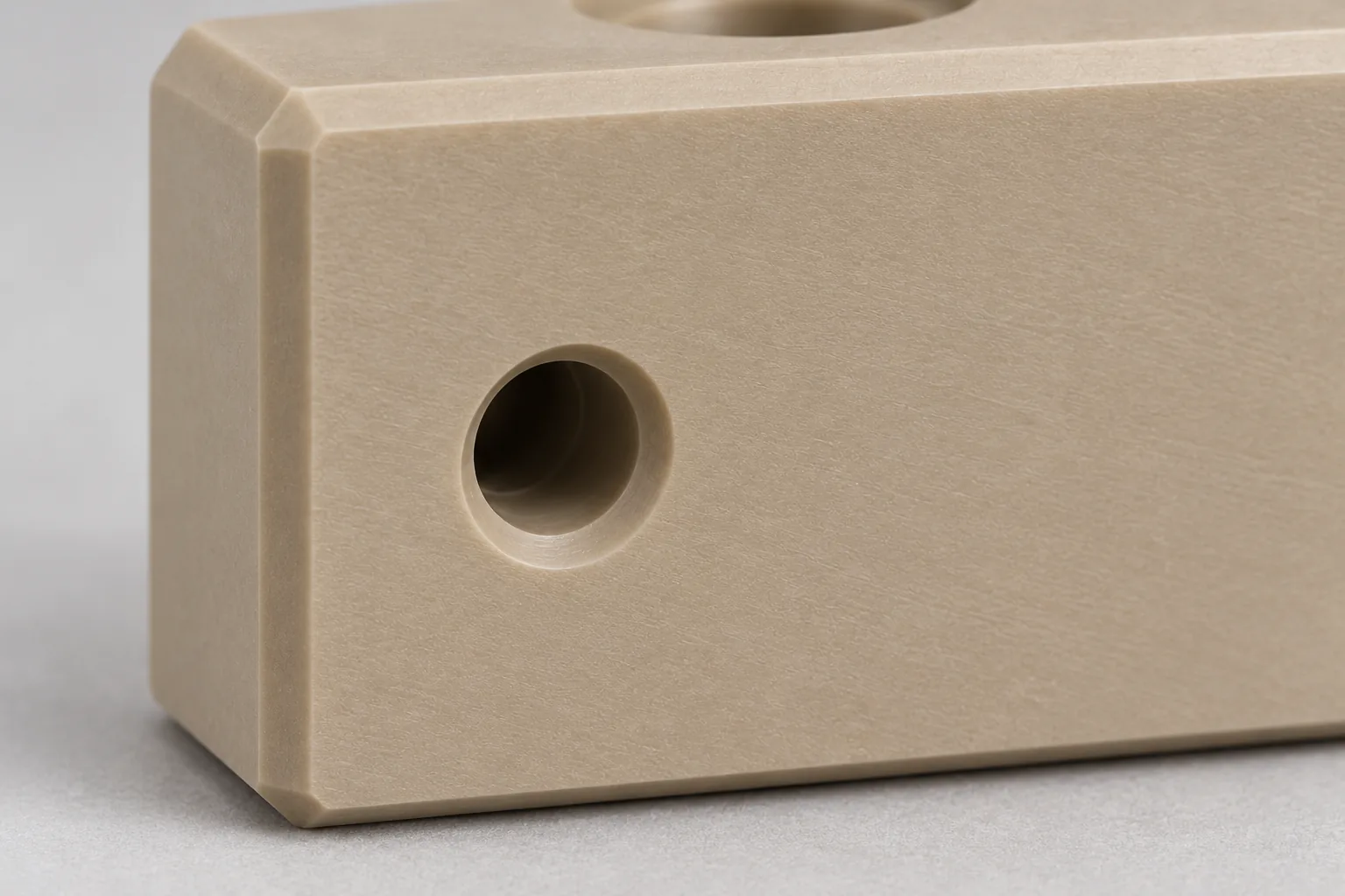
An access-aware machining route
Reconcile this proposed route with drawing, access and handling requirements:
- Review CAD, drawing and fluid map for intended connections and isolation.
- Establish stable references and low-stress support clear of sealing regions.
- Machine external geometry and provisional faces, retaining references.
- Create channels and ports; treat junction edges before losing reach and address newly created breakthroughs.
- Account for debris; finish sealing faces after burr-producing work where the drawing permits.
- Apply agreed cleaning, inspect features and perform customer-specified verification.
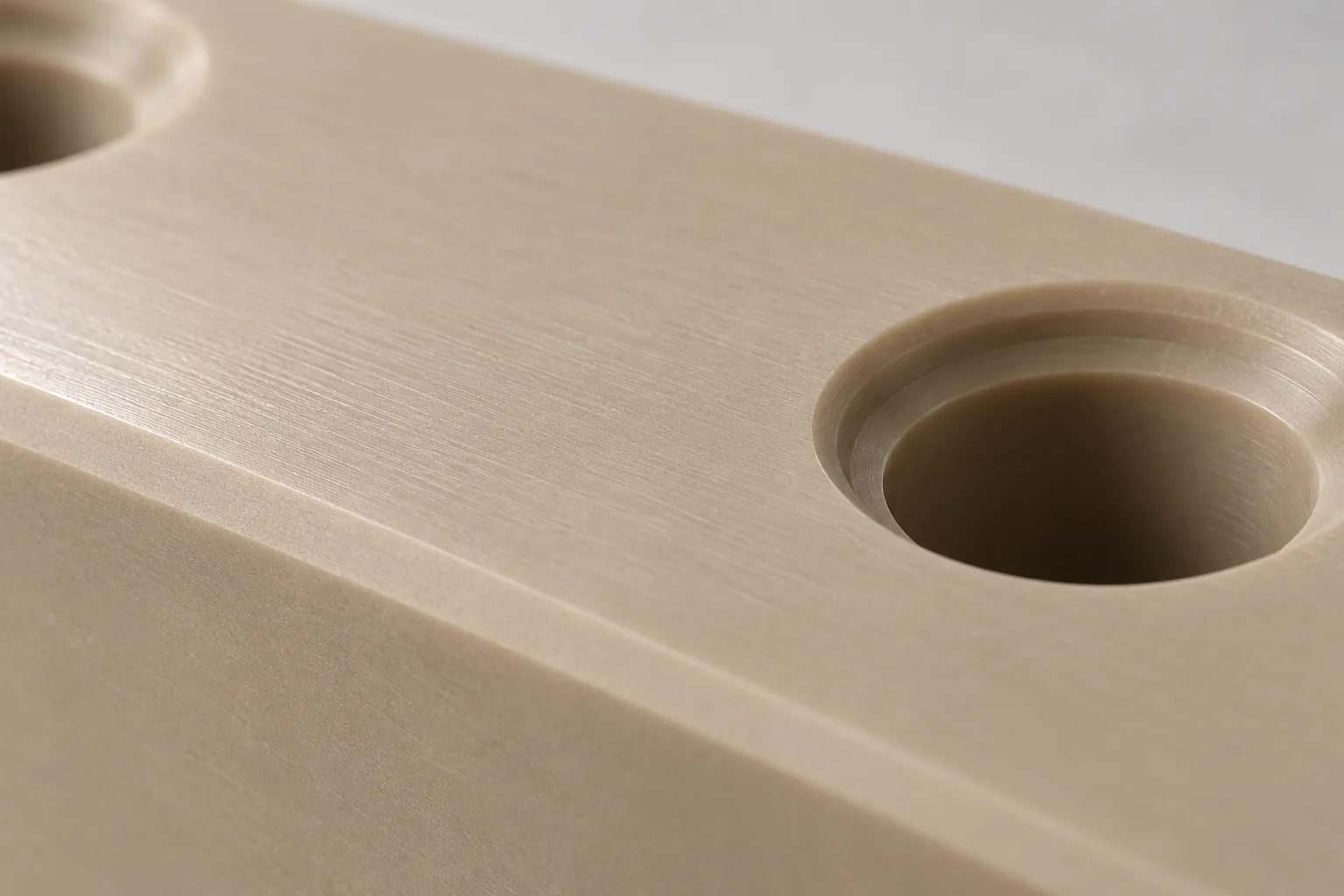
Match each feature to an observable check
Connectivity, dimensions and interface condition need distinct evidence; none alone establishes fluid-service performance.
Correct failed features and recheck. Compare acceptable delivery routes including deburring, cleaning, inspection and specified testing.
| Feature | Control intent | Typical verification |
|---|---|---|
| Sealing faces | Preserve the specified contact land and surface condition | Visual or optical examination and drawing-defined dimensional or surface checks in the required part condition |
| Channel intersections | Confirm intended connection and address accessible breakthrough edges | Flow-map review and accessible visual examination; agree a method for concealed regions |
| Port locations | Maintain the interface relationship to the drawing references | Dimensional checks against the specified datums and port definition |
| Edge condition | Avoid residual lips or edge treatment that changes the interface | Examine accessible port edges against the approved edge requirement |
Process planning
- 1. Review CAD, flow paths, drawing, and evidence limits. 2. Define stable references and low-stress workholding. 3. Machine external geometry and provisional sealing faces. 4. Create channels and ports in an access-aware sequence. 5. Deburr intersections using the approved method and finish sealing faces. 6. Clean, inspect, and perform only customer-specified verification
Quality control
| Feature / control / verification |
|---|
| Build a Feature | Control Intent | Typical Verification table for sealing faces, channel intersections, port locations, and edge condition |
| discuss visual or optical examination, dimensional checks, and customer-defined functional testing without reporting unsupplied results |
Prepare your RFQ
Native CAD, dimensioned drawing, channel map, PEEK grade, fluid compatibility requirements, port and seal definitions, tolerances, surface requirements, cleaning specification, quantity, inspection scope, and target lead time
Documented outcome and verification boundary
Publish only supported manufacturing and verification records. Do not claim leak-free service, chemical compatibility, cleanliness, or dimensional acceptance without customer-approved evidence
Sterile, biocompatible, chemically compatible, leak-free, fully compliant, burr-free by guarantee, or suitable for every diagnostic fluid
Evidence boundary and information for a machining review
Manufacturability remains unverified. Cleaning, inspection scope, test criteria, lead time and outcome: To be supplied from real project data.
Do not claim sterility, biocompatibility, chemical compatibility, leak-free operation, regulatory compliance, guaranteed burr absence or universal diagnostic-fluid suitability without applicable approved evidence.
For an access and finishing review, provide CAD, drawing, channel map, resin grade, wetted-fluid requirements, port/seal definitions, tolerances, surface and cleaning specifications, quantity, inspection scope and delivery timing.
Frequently asked questions
Can an attractive sealing face justify a fluid-service trial?
Appearance is useful for identifying visible damage, but it does not establish the mating seal's behavior or the condition of concealed passages. Use the specified interface checks and agreed functional-test criteria before treating the part as ready for its intended service.
Does switching to another PEEK grade remove the need to review the machining route?
A grade change can alter the material assumptions behind cutting and handling decisions. Review the grade together with the intended fluids, workholding and seal requirements; material selection alone does not solve a junction-access problem.
Is a routine wash sufficient when channel burrs are suspected?
Washing addresses removable contamination under the agreed protocol. It should not be assumed to detach an attached edge lip. Resolve burr-removal access separately, then assess the cleaning process against its specified objective.