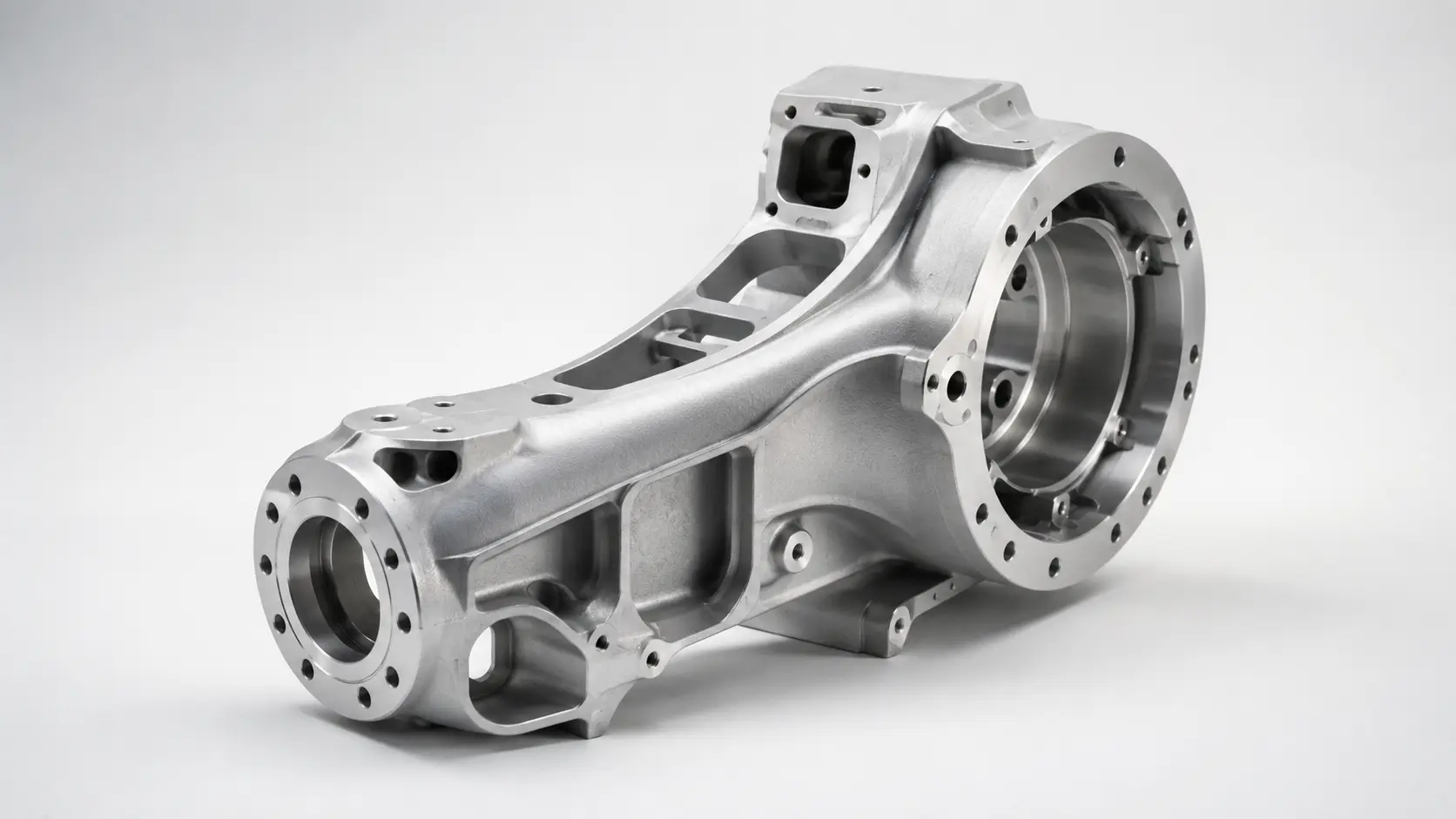
Precision Machining Case for a Robot Joint Structural Part
A robot joint housing brings large bearing bores, mounting faces and multi-directional hole patterns into one structural part. This case explains how the machining route is organized around stable datums, controlled finishing and drawing-based inspection.
CNC MillingMulti-face setup planning
Functional BoresFinish-machined after datum control
Drawing-Based QCInspection scope tied to functional requirements
Turning a complex robot-joint housing into a controlled machining plan
The documented requirement was to prepare an aluminum-alloy robot-joint structural component for functional sample validation. The geometry combines a large circular housing, a smaller coaxial interface, mounting pads, pockets and hole patterns on several faces. The manufacturing challenge is not simply removing material; it is keeping every functional interface related to a stable datum system through multiple setups.
For quotation and process review, the 3D model defines the overall geometry while the 2D drawing identifies the dimensions that influence bearing fit and assembly alignment. Those requirements determine the setup sequence, finishing operations and inspection plan.
SectorRobotics
ComponentJoint structural housing
Project stageFunctional sample validation
Public evidenceIdentity and drawing values withheld
Engineering focus
Three features drive the machining strategy
01
Bearing bore relationship
The large and small circular interfaces must be evaluated as one functional system, with bore size, position and axis relationship controlled to the drawing.
02
Multi-face datum transfer
Mounting pads and hole patterns sit on different orientations, so each setup must reference proven surfaces instead of creating an independent local origin.
03
Part stability during finishing
Material removal changes stiffness and residual stress. Roughing, stabilization and final finishing are separated to protect critical interfaces.
Process planning
A datum-led CNC workflow
The manufacturing route is organized around the functional assembly references. Exact tools, fixtures and inspection frequency are selected after the drawing, alloy grade, batch size and tolerance stack are reviewed.
DFM and drawing reviewIdentify the primary mounting datum, bearing interfaces, critical hole patterns, threads, finish requirements and inspection notes before programming.
Rough machining and stress managementRemove bulk material while leaving finishing allowance on functional faces and bores. Plan balanced cuts and support points to limit distortion.
Reference-face preparationCreate and verify the datum faces used by later setups. Fixtures locate from these references so features on different orientations remain connected.
Multi-face feature machiningMachine pockets, profiles, mounting pads, holes and threads in a controlled sequence, protecting finished references between setups.
Bore and interface finishingFinish critical circular interfaces after the structure is stable, then verify their size and relationship to the assembly datums.
Final inspection and delivery reviewInspect drawing-critical dimensions, thread condition, edge break and cosmetic requirements before the part is released for assembly validation.
Quality control
Inspection follows function, not appearance alone
The image shows the general part form, but acceptance is driven by the customer drawing. A case-specific inspection plan connects each functional feature with a suitable verification method.
Feature
Control intent
Typical verification
Bearing bores
Size, roundness and axis relationship per drawing
Bore gauge and CMM as required
Mounting datums
Flatness and relationship to functional interfaces
Surface plate, height gauge or CMM
Hole patterns and threads
Position, depth and thread condition
CMM, pin gauges and thread gauges
Profile and edge condition
Drawing conformity, deburring and handling safety
Dimensional and visual inspection
Prepare your RFQ
Information needed for an accurate robot-part quote
Providing the following information lets the quotation team select the right process, inspection scope and delivery plan without guessing at critical requirements.
3D CAD model in STEP, STP or another supported format
2D drawing with datums and critical dimensions
Required aluminum grade or approved alternatives
Tolerance and surface-roughness callouts
Post-processing, marking and cosmetic requirements
Prototype and production quantities with target date
Documented outcome and verification boundary
The documented outcome is a functional sample prepared for assembly verification, with critical interfaces checked against the customer drawing before release. Because the public case does not include the inspection report or numeric acceptance values, it does not claim a published tolerance result. What the case demonstrates is the datum-led route used to connect machining and verification decisions to the part's function.
Have a robot joint or precision structural part to manufacture?
Upload the 3D model and drawing. XPartsLab will review the machining route, material, critical dimensions, inspection needs and delivery feasibility.
This payment channel is provided by the Zouqianba payment platform.
Please use WeChat\Alipay\UnionPay QuickPass to scan the QR code to pay
After payment is completed, the system will automatically confirm the order. Please do not scan the code repeatedly.
If you have any questions, please contact your account manager:
(Same number on WeChat) / Working hours: 9:00-18:00
1. Please follow the information below to make the remittance.
Recipient bank:
Beneficiary Bank Branch:
Benefit account name:
Bank account number:
Please fill in the order number in the remarks when transferring so that you can promptly confirm the arrival of your money. If you have completed bank transfer, please click the button below to submit your order:
2. The remittance arrival cycle is generally 1 to 5 working days. After the payment arrives, we will arrange the order to enter the follow-up process.
If you have any questions, please contact your account manager:(Same number on WeChat) / Working hours: 9:00-18:00