
Project overview
Unmanned aerial imaging systems
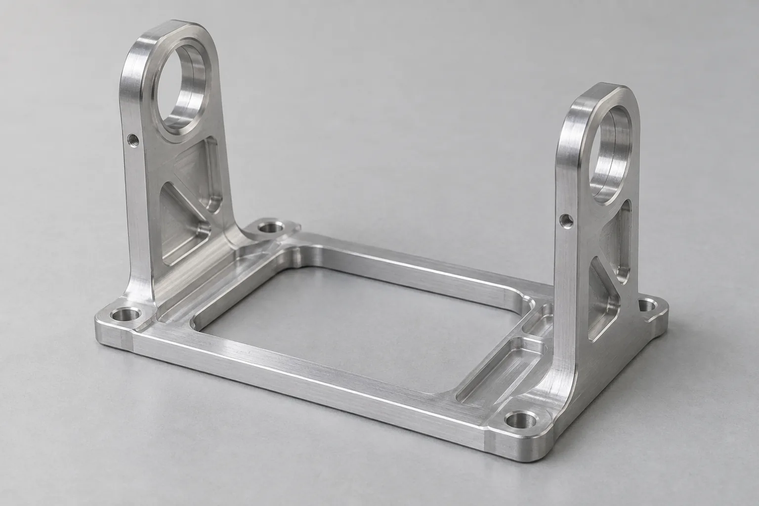
UAV camera-gimbal frame
Prototype-to-low-volume manufacturing planning; actual stage to be supplied from real project data
An editorial case direction for CNC machining a 7075 aluminum UAV camera-gimbal frame whose thin walls and multi-face interfaces create distortion and datum-transfer risks
What this case documents—and what it does not
Public evidence
No completed customer-project facts were supplied; the industry, component, material family, process, and challenge are editorial premises only
Confirm from customer files
Exact grade and temper, CAD geometry, datums, tolerances, finish, quantity, inspection scope, lead time, and outcome must be confirmed from authorized files
Keep editorial premises, confirmed customer facts, and prohibited inference visibly distinct
Engineering focus
Thin-wall stock distribution—explain why balanced roughing and controlled intermediate states affect residual-stress release
Functional datum continuity—show how bearing, motor, and mounting interfaces drive setup and reference strategy
Multi-face access and support—explain how fixture contact, tool access, and clamping sequence influence deformation risk
Application, machining route and evidence boundary
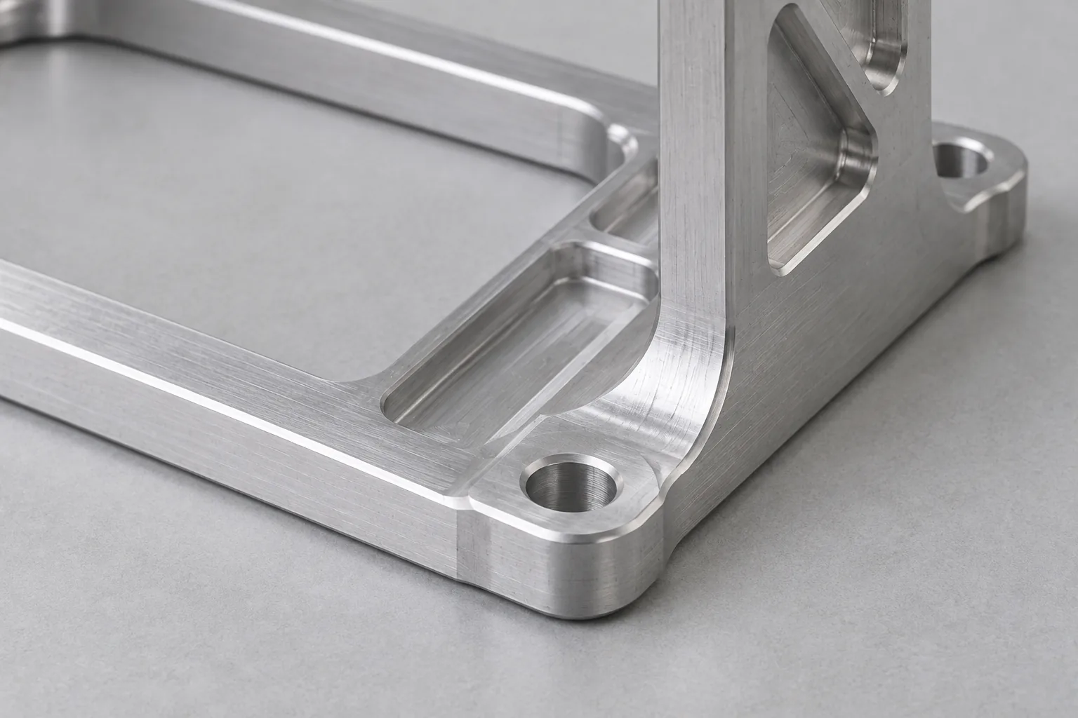
The proposed frame locates a camera and rotational interfaces in a lightweight UAV gimbal. Multi-axis milling offers access to faces and pockets from different directions; tool clearance and workholding still need review against the actual CAD model.
| Planning parameter | Current basis |
|---|---|
| Component and service | UAV camera-gimbal frame; precision CNC machining |
| Material and process | 7075 aluminum family; multi-axis milling |
| Specification inputs | Exact grade, temper, stock form, tolerances, finish and quantity require authorized project files |
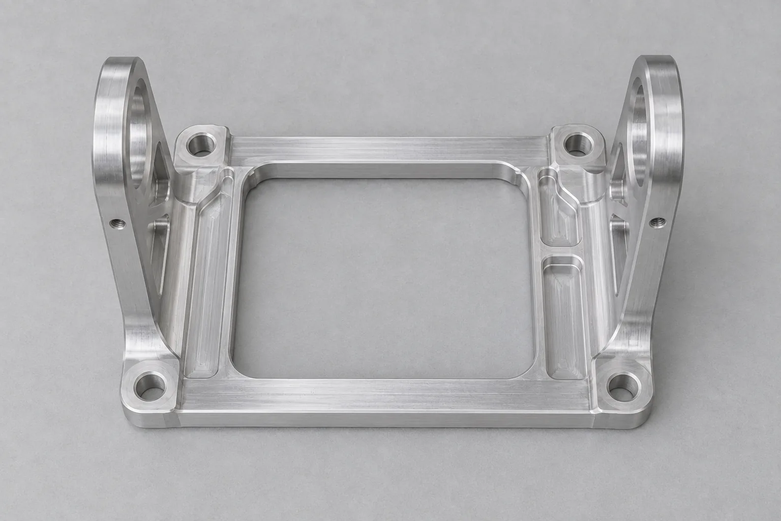
Engineering focus: removal balance, datums and support
Removing stock can release stresses already present in the blank. A slender wall has less resistance to bending, so uneven removal may leave it moving as the cut progresses or after release. Balanced roughing and intermediate allowances are proposed ways to limit this risk. If the free-state profile changes, investigate stock condition and machining sequence before correcting tool offsets.
A datum is the reference used to locate and evaluate other features. Bearing, motor and mounting interfaces should guide reference selection. Where an interface crosses setups, check how the reference is transferred; a repeatable fixture position alone does not establish the assembled relationship.
Clamp force can bend a wall that appears stable during cutting. Support near the working region can help, provided it leaves tool access and does not preload the part. Compare the released shape with the supported condition. Movement tied to release calls for a workholding review; disagreement between faces also calls for checking reference transfer.
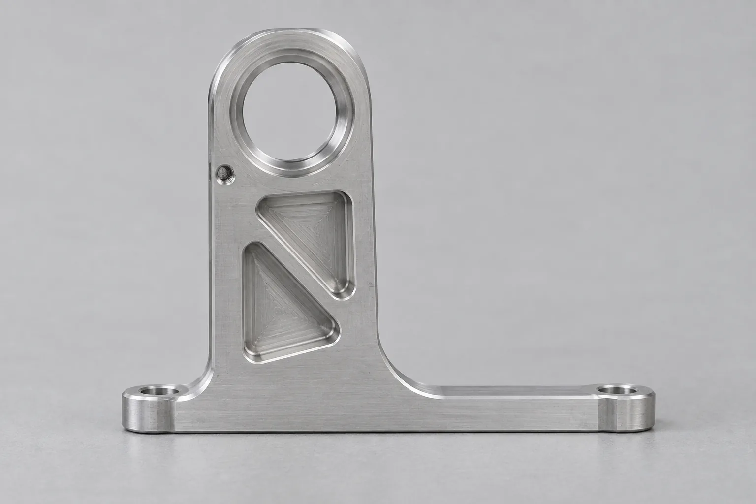
Proposed connected machining sequence
Carry the assembly references through the plan, and inspect intermediate states before removing the remaining allowance. Drawing review may change this sequence.
- Review the CAD and drawing for interface relationships, access restrictions and inspection references.
- Assess stock form, temper evidence and areas where uneven removal could release stress.
- Rough opposite regions in a balanced sequence, retaining allowance for subsequent operations.
- Prepare reference faces and check that locating contact does not rock or bend the frame.
- Semi-finish accessible faces, then finish critical interfaces using the agreed datum strategy.
- Deburr, coordinate specified post-processing, and inspect in the required final condition.
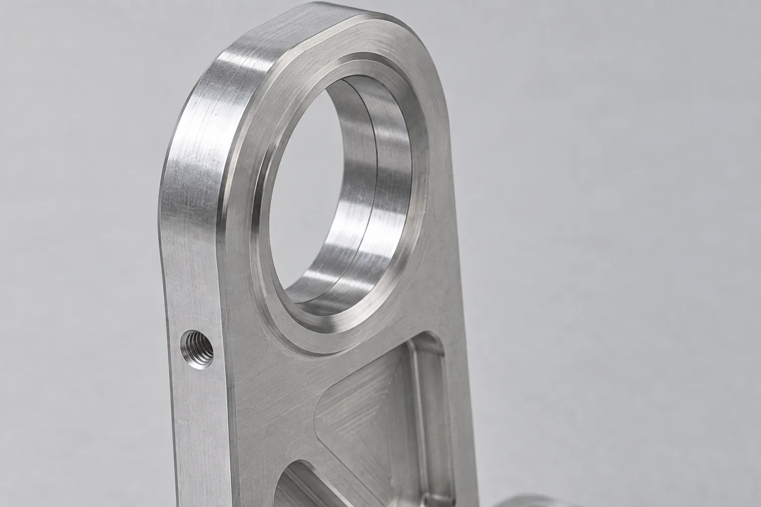
Quality checks that guide the next decision
Choose verification methods for the feature and required acceptance condition. The options below are typical methods, not tests performed on this frame. If an interface fails its drawing requirement, establish whether the issue is local geometry, reference transfer or released deformation before selecting rework.
| Feature | Control intent | Typical verification |
|---|---|---|
| Frame profile | Detect released shape movement | Optical or CMM comparison using agreed support conditions |
| Bearing interfaces | Check fit geometry and alignment | Suitable gauges and coordinate inspection |
| Mounting datums | Establish usable reference contact | Surface evaluation and seating check |
| Hole patterns | Relate position to assembly references | Coordinate inspection against the datum scheme |
| Edge condition | Protect mating surfaces and handling | Visual inspection of specified edge treatment |
Upload your drawings for a usable quotation
Prepare the information below so the machining review can identify access conflicts, support needs and acceptance criteria. Discuss the project with these inputs to decide whether the proposed milling route is suitable or needs a different setup strategy.
- 3D CAD plus a matching 2D drawing.
- Material designation, temper and specified surface finish.
- Datum scheme, tolerances and camera, motor or bearing mating interfaces.
- Quantity, target lead time and application environment.
- Inspection scope and any requirements after finishing.
Process planning
- Present 6 connected steps: drawing and DFM review
- stock and stress-risk assessment
- symmetric roughing with allowance
- reference-face preparation
- multi-face semi-finishing and critical-interface finishing
- deburring, post-processing coordination, and final inspection. Describe each as a proposed method subject to drawing review
Quality control
| Feature / control / verification |
|---|
| Use Feature | Control Intent | Typical Verification for frame profile, bearing interfaces, mounting datums, hole patterns, and edge condition |
| mention CMM, gauges, or optical methods only as typical options, not performed facts |
Prepare your RFQ
3D CAD, 2D drawing, material and temper, datum scheme, tolerances, surface finish, quantity, assembly interfaces, application environment, inspection requirements, and target lead time
Documented outcome and verification boundary
The eventual article may prove only what customer files and approved inspection evidence support; no numerical result is currently confirmed, and one frame cannot establish universal capability
Do not claim zero distortion, perfect inspection, guaranteed tolerance, fixed lead time, reduced cost, or production success
What would support an outcome claim?
Authorized customer files and approved inspection records establish a delivered result. Review comparable lightweight frames against their own wall geometry, stock condition and assembly relationships. An individual frame would not demonstrate universal capability; quotation assumptions should remain traceable through final verification.
Frequently asked questions
Does specifying 7075 aluminum settle the stock choice?
The family name leaves temper and stock form open. Obtain those details before assessing stress risk or deciding whether the proposed machining sequence is appropriate.
Can surface finishing be treated as a separate purchasing step?
Its drawing requirements belong in the machining review because the finished interfaces must meet the agreed acceptance condition. Specify whether inspection is required after processing.
Why can a prototype result fail to predict a later batch?
Different stock condition or locating contact can change the released shape. Compare those inputs with the prototype records before carrying its process assumptions forward.
Is additional machining allowance always the remedy?
Allowance provides room for later cuts, but cannot resolve a wall bent by clamping. Establish when movement appears before deciding whether to alter support or removal order.