Support Hours: 09:00–18:00 (GMT+8) · Messages and quote requests are accepted 24/7.
Material Database

Carbon Fiber Sheet

CNC composite material sheets suitable for making lightweight structural parts, high-rigidity panels, drone parts, robot structural parts, sports equipment accessories, equipment panels, fixtures and fixtures, and high-end tech-inspired exterior parts.

Material description

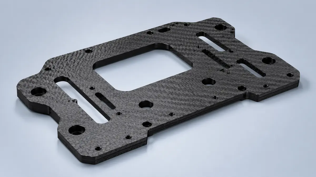
Carbon Fiber Sheet is a carbon fiber composite sheet processed by CNC cutting, milling, drilling, and other methods, usually cured by composites such as carbon fiber cloth and epoxy resin. It features light weight, high strength, good rigidity, fatigue resistance, a strong technological appearance, and good dimensional stability. It is commonly used in drone structural parts, robot brackets, sports equipment, equipment panels, fixtures and jigs, lightweight structural panels, and high-end decorative parts. Compared to aluminum alloy, Carbon Fiber Sheet is lighter; Compared to ordinary plastic boards, it offers better rigidity and strength, but it requires focused control over processing dust, delamination, chipping, and hole edge strength.

Carbon Fiber SheetCNC Carbon Fiber SheetCarbon plateCarbon fiber composite panelsCarbon fiber laminateCarbon fiber sheetsCarbon fiber panelsCarbon fiber structural panelsCarbon fiber processed partsCarbon Fiber Plate
The Carbon Fiber Sheet of CNC offers obvious advantages in lightweight design and high rigiditySuitable for making tabletsStencing typesFrame and structural connection partsCarbon Fiber Sheet typically has high strength and rigidity along the fiber lamination directionHowever, the interlayer orientation is relatively weakHole edgeEdges and thin bridge positions are prone to delaminationRisk of chipping or crackingIt is not suitable for direct tapping of strong threads like metal
Carbon Fiber Sheet
CNC MachiningPlastics

Material compatibility assessment

By focusing on application scenarios, boundaries of advantages, and non-recommended scenarios, it helps sales, customer service, and quoting staff quickly determine whether the material meets current part requirements.

Core advantages

Lightweight, high strength, good rigidity, excellent specific strength, good fatigue resistance, strong technological appearance, suitable for lightweight design, suitable for plate-like structural parts, good dimensional stability, and can be contour cutting and hole machining via CNC.

Suitable for the product

Drone racks, robot brackets, equipment panels, instrument panels, structural connection boards, lightweight support panels, sports equipment accessories, model aircraft parts, racing car modification parts, fixture and jig boards, decorative panels, high-end consumer product appearance parts, mechanical partitions, positioning boards, lightweight mounting plates, and small-batch structural samples.

Not suitable for the product

High impact toughness parts, large deformation clips, high compression deformation parts, complex three-dimensional curved parts, strong threaded connectors, high wear-resistant sliding parts, food direct contact parts, medical implants, parts requiring metal conductivity stability, parts requiring strong welded structures, heavy load-bearing parts, and scenarios where dust control requirements cannot be met.

Key parameter references

The following parameters come from product information and material knowledge fields, used for design review, quotation communication, and preliminary judgment before material selection.

Material positioningCNC composite material sheets suitable for making lightweight structural parts, high-rigidity panels, drone parts, robot structural parts, sports equipment accessories, equipment panels, fixtures and fixtures, and high-end tech-inspired exterior parts.
Precision performanceCNC Carbon Fiber Sheet suitable for planar contours, hole positions, slots, windows, and simple plate structures, achieving good profile and hole position accuracy. Actual accuracy is affected by sheet thickness, lamination quality, tool condition, clamping method, machining parameters, fiber orientation, and edge delamination. For positioning holes, assembly holes, and porous structures, hole position tolerances, hole edge quality, and edge burrs should be controlled separately.
Dimensional tolerancesConventional dimensional tolerances for CNC machining Carbon Fiber Sheet can be referenced ±0.05mm-±0.15mm, while ordinary plate structural parts can be evaluated at ±0.10mm-±0.30mm. Large panels, thin panels, densely perforated parts, complex window openings, and parts with high appearance requirements may need to be evaluated separately based on the structure. These values are standard reference ranges and are not absolute guaranteed tolerances for all structures. Positioning holes, assembly holes, and appearance edges should be separately marked with tolerances and quality requirements.
Minimum Wall ThicknessCarbon Fiber Sheet usually select materials based on panel thickness, common thicknesses include 0.5mm, 1.0mm, 1.5mm, 2.0mm, 3.0mm, 5.0mm, etc. For ordinary structural parts, the recommended plate thickness should not be less than 1.0mm; for structures bearing assembly forces, screw tightening, support, or bending resistance, it is recommended not less than 1.5mm-2.0mm. It is not recommended to design thin bridges, narrow edges, and small hole peripheries that are too thin.
Recommended wall thicknessStandard exterior panels and decorative panels are recommended at 1.0mm-2.0mm; drone racks, robot brackets, lightweight connection plates, and structural support plates are recommended at 2.0mm-4.0mm; Locations bearing heavy loads, screw tightening, or requiring high bending resistance are recommended at least 3.0mm, and reliability can be improved by increasing hole margins, adding rounded corners, and local reinforcement.
Minimum apertureCNC drilling or milling is recommended to have a hole diameter of no less than 1.0mm. Small holes, dense holes, and holes near the edges are prone to burrs, delamination, or cracking at the edges. It is recommended to reserve sufficient hole margins for screw holes, positioning holes, and assembly holes, and the holes should be chamfered or countersunk. For important load-bearing holes, consider adding metal gaskets, inserts, or local reinforcement structures.
Assembly clearanceFor ordinary assembly, it is recommended to reserve 0.10mm-0.30mm on one side; for multi-hole positioning and panel assembly, it is recommended to reserve 0.10mm-0.20mm based on hole position accuracy, surface treatment, and assembly method. Carbon Fiber Sheet is not suitable for forced interference assembly; overly tight assembly can easily cause delamination or cracks at the hole edges. It is recommended to use shims, limiting posts, or metal inserts to tighten the screw tightening position to avoid localized damage to the panel.
Detailed performanceCNC Carbon Fiber Sheet suitable for machining holes, grooves, windows, fillets, chamfers, contours, countersunk holes, and simple markings. Small sharp corners, narrow bridges, elongated strips, and tiny text can easily cause chipping, layering, or fibrous burrs. It is recommended to use silkscreen printing, laser marking, labeling, or surface spraying for exterior logos; it is not recommended to design overly fine hollowed-out textures in high-stress areas.
Surface effectCarbon Fiber Sheet raw surface is usually black carbon fiber texture, which can appear as twill, plain, or unidirectional textures, giving a strong technological feel. The surface can be matte, semi-glossy, or glossy, depending on the panel resin and post-processing method. CNC-machined edges are usually black or dark gray cross-sections, with visible laminated structures and fiber textures. After chamfering, sanding, and varnishing, the edges and surface texture will be even better.

Typical application scenarios

Based on material characteristics and suitable product ranges, customer needs are broken down into easier application directions to determine.

Product validation

Drone racks, robot brackets, equipment panels, instrument panels, structural connection boards, lightweight support panels, sports equipment accessories, model aircraft parts, racing car modification parts, fixture and jig boards, decorative panels, high-end consumer product appearance parts, mechanical partitions, positioning boards, lightweight mounting plates, and small-batch structural samples.

Reasons for material selection

CNC composite material sheets suitable for making lightweight structural parts, high-rigidity panels, drone parts, robot structural parts, sports equipment accessories, equipment panels, fixtures and fixtures, and high-end tech-inspired exterior parts.

Material characteristics

CNC Carbon Fiber Sheet has obvious advantages in lightweight weight and high rigidity, making it suitable for manufacturing flat plates, brackets, frames, and structural connection parts. Carbon Fiber Sheet typically have higher strength and rigidity along the fiber lamination direction, but weaker interlayer directions, making the hole edges, edges, and thin bridge positions prone to delamination, chipping, or cracking. It is not suitable for direct tapping of strong threads like metal, nor for structures that withstand long-term heavy impact or large deformation.

Design and risk review

Based on wall thickness, hole position, assembly clearance, dimensional tolerances, and material usage risks, determine in advance whether the part structure is suitable for Carbon Fiber Sheet.

Design considerations

  • When designing CNC Carbon Fiber Sheet parts
  • Emphasis should be placed on the direction of force application
  • Fiber laying
  • The planks are thick
  • Hole margins
  • Rounded edges and assembly method
  • For interior corners, it is recommended to add fillet corners
  • Avoid stress concentration at sharp corners
Precision performanceCNC Carbon Fiber Sheet suitable for planar contours, hole positions, slots, windows, and simple plate structures, achieving good profile and hole position accuracy. Actual accuracy is affected by sheet thickness, lamination quality, tool condition, clamping method, machining parameters, fiber orientation, and edge delamination. For positioning holes, assembly holes, and porous structures, hole position tolerances, hole edge quality, and edge burrs should be controlled separately.
Dimensional tolerancesConventional dimensional tolerances for CNC machining Carbon Fiber Sheet can be referenced ±0.05mm-±0.15mm, while ordinary plate structural parts can be evaluated at ±0.10mm-±0.30mm. Large panels, thin panels, densely perforated parts, complex window openings, and parts with high appearance requirements may need to be evaluated separately based on the structure. These values are standard reference ranges and are not absolute guaranteed tolerances for all structures. Positioning holes, assembly holes, and appearance edges should be separately marked with tolerances and quality requirements.
Quality riskThe main risks CNC Carbon Fiber Sheet include processing dust, edge delamination, hole edge cracking, fiber burrs, weak thread connection ability, insufficient interlayer strength, and scratches on the surface surface. It is suitable for lightweight and high-rigidity boards, but not for direct tapping, welding, or forceful interference assembly as a regular metal sheet. When used for drones, robots, equipment panels, and moving structural components, special attention should be paid to the direction of force application, plate thickness, hole edge spacing, fillets, edge closure, and assembly methods.
Surface effectCarbon Fiber Sheet raw surface is usually black carbon fiber texture, which can appear as twill, plain, or unidirectional textures, giving a strong technological feel. The surface can be matte, semi-glossy, or glossy, depending on the panel resin and post-processing method. CNC-machined edges are usually black or dark gray cross-sections, with visible laminated structures and fiber textures. After chamfering, sanding, and varnishing, the edges and surface texture will be even better.

Post-processing and assembly precautions

Post-processing of Carbon Fiber Sheet affects appearance, dimensions, hole position, assembly clearance, and usage validation results, and should be explained in advance during quotation, DFM review, and sample confirmation stages.

Post-processing options

Post-processing should focus on appearance display, dimensional fitting, connection assembly, and testing verification. Parts involving assembly positions need to be reserved in advance for machining, coating, and trial assembly allowances.

CNC cuttingCNC cutting is used to improve the appearance, assembly, or validation of parts, and must be combined with material properties to confirm dimensions, strength, and delivery impact.
CNC millingCNC milling is used to improve part appearance, assembly, or usage validation, requiring confirming dimensions, strength, and delivery impact based on material properties.
DrillingDrilling is used to improve the appearance, assembly, or validation of parts, and must be combined with material properties to confirm dimensions, strength, and delivery impact.
GroovingSlotting is used to improve the appearance, assembly, or validation of parts, and must be combined with material properties to confirm dimensions, strength, and delivery impact.
ChamferChamfering is used to improve the appearance of parts, assembly, or functional verification effects, and the dimensions, strength, and delivery impact need to be confirmed in combination with material characteristics.
Edge polishingEdge grinding is used to improve the appearance, assembly, or validation of parts, and must be combined with material properties to confirm dimensions, strength, and delivery impact.
Edge banding treatmentEdge banding is used to improve the appearance, assembly, or validation of parts, and must be determined by material properties to confirm dimensions, strength, and delivery impact.
Cleaning and dust removalCleaning and dust removal are used to improve the appearance, assembly, or validation of parts, and must be determined by combining material properties with dimensions, strength, and delivery impact.

Key control point

Size impactCarbon Fiber Sheet processing generates carbon powder and resin dust; Proper vacuuming is necessary; Protection and cleaning; Burrs are likely to form at the machining edges; Layering and edge collapse; It is recommended to use sharp knives; Reasonable speed feed and edge chamfering treatment; After machining the hole positions and edges, it is recommended to seal or apply adhesive for protection
Assembly clearanceFor positions involving snapping, plugging, sliding, or enclosure closure, the clearance needs to be adjusted according to post-processing thickness, material shrinkage, and trial assembly results.
Hole Position StrengthThreading, inserting nuts, locking screws, and the areas around positioning holes need to ensure wall thickness to avoid cracks, stripped threads, or chipped edges during post-processing or assembly.
Environmental matchingWhen used in high-temperature, outdoor, humid, friction, or load-bearing scenarios, post-processing materials, adhesives, coatings, and fasteners must also meet the corresponding usage environment.

Structure and usage boundaries

For common issues such as threads, snaps, strength, temperature resistance, and weather resistance, identify in advance whether the material needs to be replaced or if another processing method should be used.

Thread Recommendation

Applicable ScopeCarbon Fiber Sheet not suitable for directly processing high-strength threads, nor for frequently removing and assembling threads.
Risk pointFor ordinary panel connections, it is recommended to use through-hole screws, nuts, gaskets, metal inserts, pressure rivets, aluminum posts, or screw column structures.
Recommended practiceWhen tightening screws, avoid excessive tightening. It is recommended to use large washers or limit posts to disperse pressure and prevent hole edge cracking, delamination, or surface damage.

Buckle recommendation

Applicable ScopeCarbon Fiber Sheet is not suitable for designing large deformation elastic buckles like plastic.
Risk pointIt can design slots, positioning holes, pressure plate fixing, screw fixing, pin positioning, adhesive bonding, or low-deformation slot structures.
Recommended practiceIf elastic snaps are needed, materials such as Acetal (POM), Nylon (PA), Polycarbonate (PC), ABS, spring steel, or metal spring plates should be selected. Carbon Fiber Sheet is more suitable for rigid connections and plate supports, and not suitable for long-term repeated elastic deformation.

Strength and Environment

Mechanical strengthCarbon Fiber Sheet has very high specific strength and specific stiffness, performing excellently along the fiber direction, making it suitable for lightweight, high-rigidity structural components.
Environmental boundaryIts interlayer strength, impact toughness, and hole edge bearing capacity require focused design and cannot be simply equated with metal plates.
Recommended practiceThe load-bearing structure should be verified based on plate thickness, fiber orientation, layering method, hole edge spacing, connection method, and safety factor. Carbon fiber bodies have good temperature resistance, but the actual temperature resistance of Carbon Fiber Sheet is mainly affected by the epoxy resin matrix. Ordinary Carbon Fiber Sheet is not recommended for long-term use in excessively high temperatures, as high temperatures may cause resin to soften, reduce strength, delaminate, or discolor on the surface. If used in high-temperature environments, a high-temperature resistant resin system Carbon Fiber Sheet should be selected, and validated based on specific temperature, load, and usage time. Carbon Fiber Sheet body has good corrosion resistance and does not rust like steel, but long-term UV exposure, humid heat, salt spray, and outdoor environments may affect the resin surface, varnish layer, and edge sealing performance. For outdoor or high-humidity environments, it is recommended to apply edge sealing, transparent protective paint, or weather-resistant coatings, and avoid exposing exposed edges for extended periods of moisture absorption. When connecting with aluminum alloys, stainless steel, or other dissimilar metals, attention should be paid to electrochemical corrosion isolation.

Alternative material selection and final judgment

When customer demand exceeds Carbon Fiber Sheet material boundaries, it is necessary to combine strength, temperature resistance, toughness, long-term stability, and mass production goals to promptly recommend alternative materials or processing technologies.

Alternative material suggestions

If better metalworkability and threaded connection ability are required,6061 Aluminum Alloy or 7075 can be chosen; If higher impact toughness is required, Polycarbonate (PC), nylon, Nylon (PA)66, or aluminum alloy can be chosen; If lower-cost panels are needed, FR4, ABS, Acetal (POM), or aluminum panels can be chosen; If higher temperature resistance and insulation performance are required, FR4, Polyether Ether Ketone (PEEK), or PPS can be chosen; If complex three-dimensional surfaces are needed, carbon fiber molded parts, composite material laminates, or 3D printed prototypes can be considered.

Material selection suggestions

If customers mainly care about lightweight, high rigidity, a tech-inspired appearance, and the strength of the plate structure, CNC Carbon Fiber Sheet is a very suitable choice. If customers need to frequently remove and assemble threads, have high impact toughness, complex curved surfaces, or low-cost ordinary structural parts, it is not recommended to prioritize Carbon Fiber Sheet; instead, consider aluminum alloy, Acetal (POM), FR4, Polycarbonate (PC), or other engineering materials. When selecting materials, focus should be paid to the slab thickness, laying direction, appearance surface, hole position, force direction, and assembly method.

Already have the blueprints? Directly enter the quotation for custom parts

After uploading 3D/2D drawings and supplementing materials, quantities, tolerances, surface treatments, and delivery requirements, XPartsLab will provide next steps in 3D printing manufacturability, cost, and delivery pathways.